_______________________________________________________________________________________________________________________________________________________
6
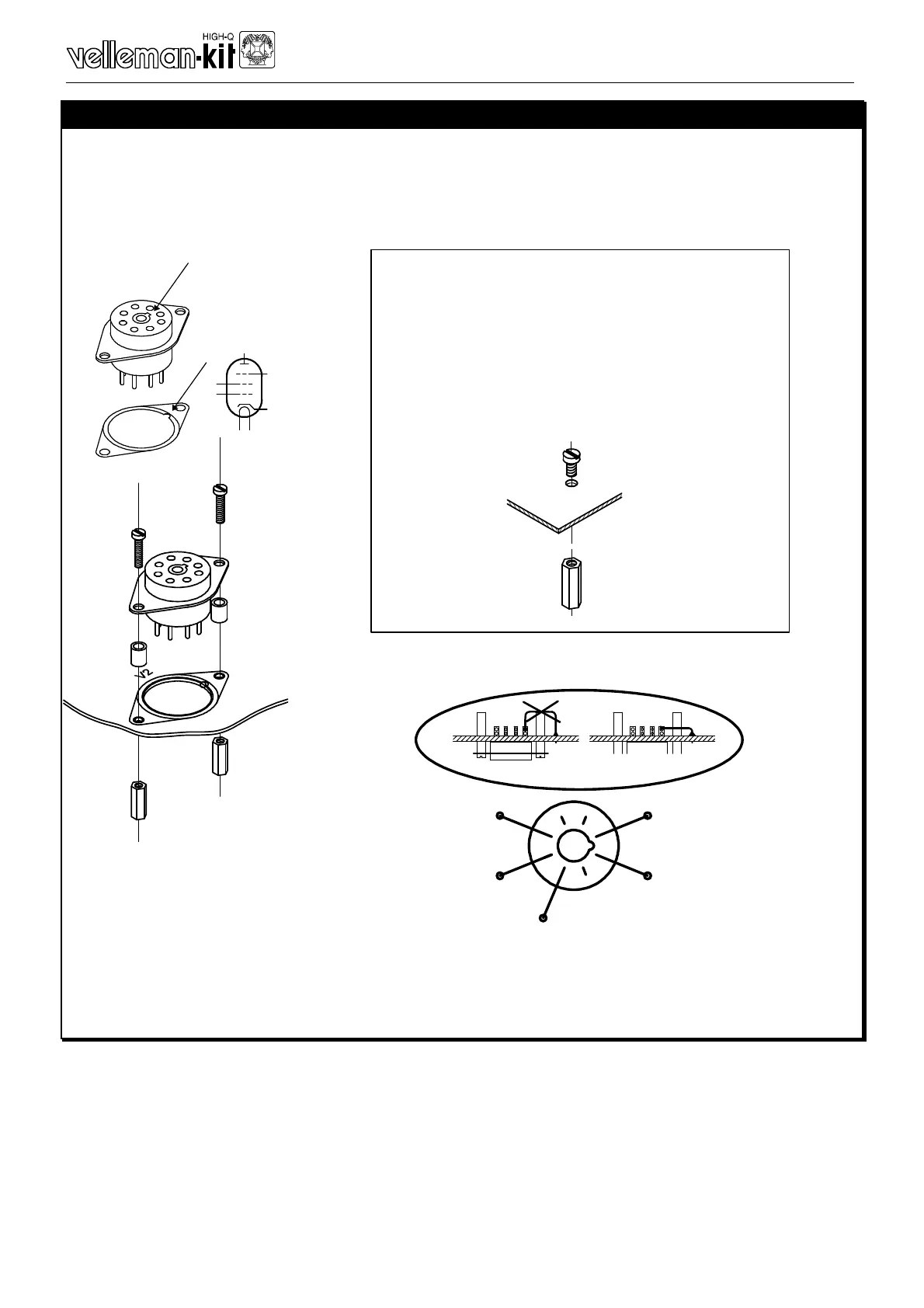
15mm M3 SPACER
12mm SPACER
PCB
20mm M3 BOLT
1. VALVE SOCKET MOUNTING
Check the position of the notch in the centre of the valve socket, it must correspond to the position of the
notch in the circle printed on the PCB. Connect the leads to the corresponding isles on the PCB using a
small piece of supplied jumper wire.
IMPORTANT:
Make the connection exactly as shown in the illustration, otherwise the small piece of wire could touch
the bottom of the cabinet, see further.
2
3
4
1
3
5
7
4
6
5
8
1
8
q V1
q V2
q V3
q V4
Also mount a 15 mm spacer on the following holes in
the PCB (at the solder side); use a 6 mm M3 bolt:
q A spacer next to TRAFO1
q A spacer next to SK15
q A spacer next to SK6
q A spacer next to R62
q A spacer next to V6
6mm M3 BOLT
15mm M3 SPACER
Connect the valve socket terminals 1, 3, 4, 5, and 8 to the corresponding
points at the solder side of the PCB.
Use a piece of supplied jumperwire. Mount the wire in such way that it can-
not touch the bottom of the cabinet. (see above illustration).


 To Next Page