4. CONTROL
4.1 INSTALLATION OF THE CONTROL
18
WARNING
Always disconnect the unit before making any connections. Failure in
disconnecting power could result in electrical shock or damage of the
control or electronic module of the unit.
CAUTION
Never install more than one optional control per unit.
1. Determine the more convenient location for the control.
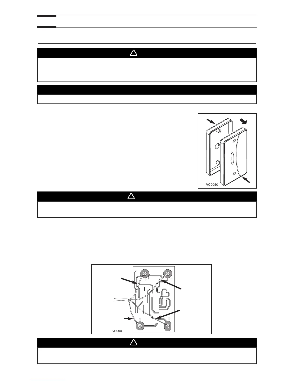
2. Remove the cover plate control (1). If you prefer to mount
the control on an approved outlet box or an approved
mounting bracket (not included), discard the backplate (2).
3. Take one end of the cable and pass it through the control backplate (or outlet box or
mounting bracket).
4. Splice back this end of the cable to access the 4 wires. Remove the insulated sleeve
of each wire ends. Make a loop with each bare end wire to hook them to their
corresponding screw. Connect YELLOW wire to “Y” screw, RED wire to “R” screw,
GREEN to “G” screw and BLACK to “B” screw. See illustration below.
1
2
WARNING
To avoid risk of electrical shocks, never install another wire in the same
electrical box than the one for the control.
BLACK
wire
YELLOW
wire
GREEN
wire
RED
wire
WARNING
Make sure that the wires don’t short circuit between themselves or by
touching any other components on the control.