13
Use the terminal connector included, by unplugging it rst, to perform the electrical connection for main wall control. Use
screws to x wires in the terminal connector. Check if all wires are rmly connected in their corresponding holes in the
terminal connector by slightly pulling on each wire.
Gnd
D+
12V
D-
VC0241
12V
D-
D+
Gnd
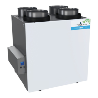
Once the wall control connections have been made, insert the terminal connector in the electrical compartment.
unit bottom view
terminAl connector
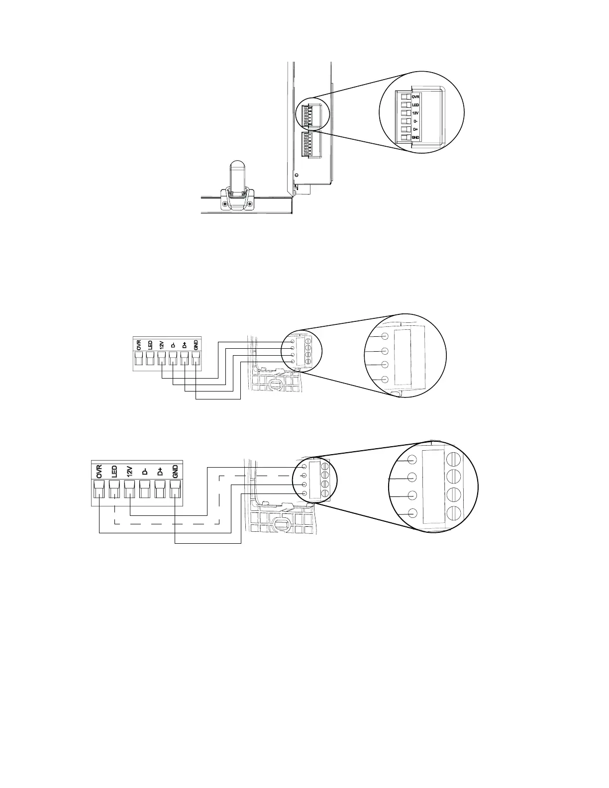
3.3 electricAl connection to 20-40-60 optionAl AuxiliAry wAll control (pArt no.204060r)
Gnd
OVR
12V
LED
C0243
Gnd
OVR
12V
LED
NOTE : The auxiliary wall control can be used with a 3-wire connection by removing the LED signals. This optional wiring
will not allow an installation with more than 1 auxiliary wall control to properly synchronize their LEDs on an event
requested from a peer. Only the auxiliary wall control having requested the timer event will have the LEDs updated
accordingly.
3.2 electricAl connection to AutomAtic mAin wAll control (pArt no.41404)
NOTE: To avoid miswiring, refer to the notes taken at step of section 3.1 to match the wire color with the right
terminal.
Plug the ventilation unit and test the wall control.
NOTE : For more information about the installation and operation of the auxiliary wall control, refer to the included
Installation and User Guide, which is also available at www.venmar.ca.
NOTE : The auxiliary wall control is connected to the same connector as the main wall control.
 Loading...