15
For the Installer
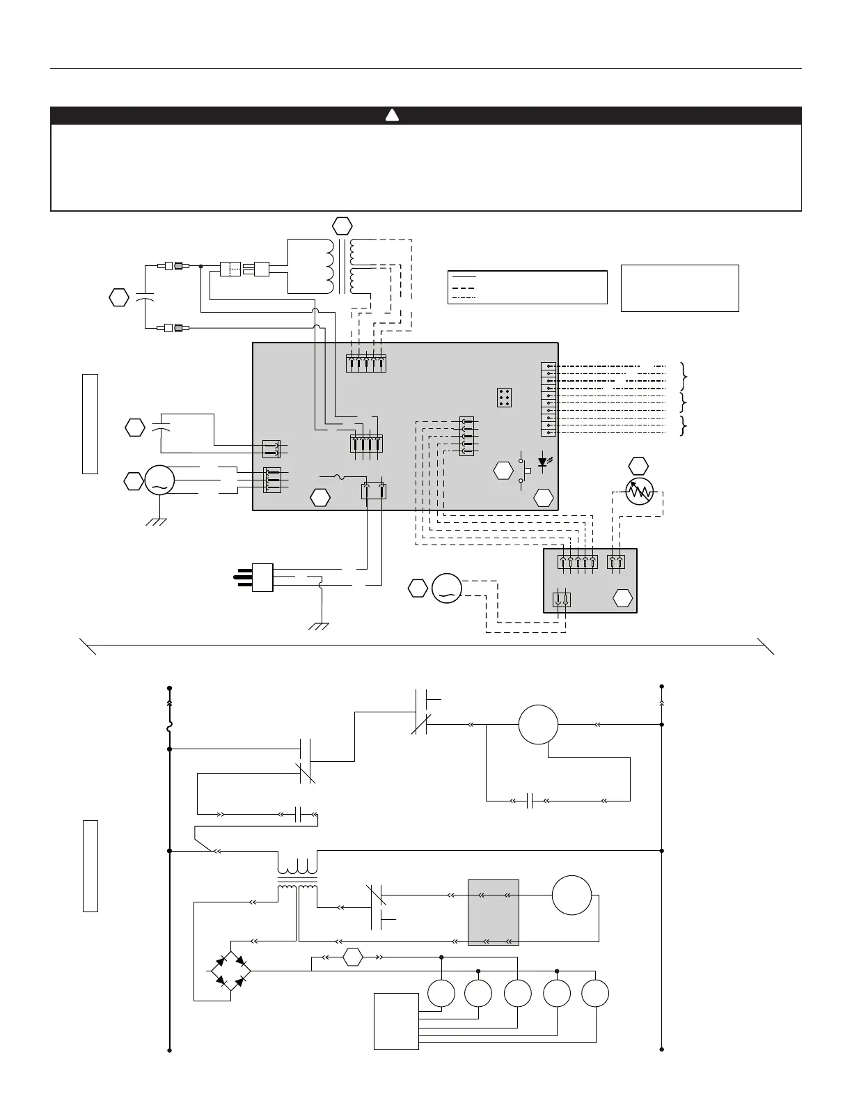
9. WIRING DIAGRAMS
• Risk of electric shocks. Before performing any maintenance or servicing, always disconnect the unit from its
power source.
• This product is equipped with an overload protection (fuse). A blown fuse indicates an overload or a short-circuit
situation. If the fuse blows, unplug the product from the outlet. Discontinue using the unit and contact technical
support.
WARNING
!
BK
W
G
A1
J6
1
2
J10
1
2
J14
10
9
8
7
6
5
4
3
2
1
12345
J12
J13
ICP
21345
J8
4321
J9
24 V Class 2
9.5 V
Class 2
C1
5 µF
2154321
12
J3
J2
J1
M2
A2
C2
F1
T1
120 VAC
60 Hz
S1
OVERRIDE SWITCH
(OPTIONAL)
F
IELD WIRING
REMOTE
CONTROL
FURNACE BLOWER
INTERLOCK
(OPTIONAL)
T
HERMISTOR
DAMPER ELECTRONIC
ASSEMBLY
ELECTRONIC ASSEMBLY
DAMPER MOTOR
3A
3AG T
YPE
COLOR CODE
t˚
VE0335A
M
J4-1
J9-3
J6-1
J6-2
J4-2
M
J2-1
J3-1
J3-2J2-2
J12-2
K4
K3
K2
T1
+-
~
~
L
INE
N
EUTRAL
120 VAC
A2
DAMPER MOTOR
BLOWER MOTOR
C1
M
OTOR
C
APACITOR
CPU
K2 K3 K4
3A
J12-1
J10-2
J10-1
J4-3
J9-1
24 VAC
9.5 VAC
C2
M
OTOR
S
PEED
J8-4
J8-5
J8-2
J8-1
LOGIC DIAGRAM
WIRING DIAGRAM
M1
BL
BR
J4
1
2
3
BK
B
G
R
R
G
BK
Y
Y
OL
OC
I
LINE VOLTAGE
CLASS 2 LOW VOLTAGE FACTORY WIRING
CLASS 2 LOW VOLTAGE FIELD WIRING
13 µF
BLACK
BLUE
BROWN
GREEN
BK
BL
BR
G
O
RANGE
RED
WHITE
YELLOW
O
R
W
Y
O
O
Y
Y
R1
BLOWER
MOTOR
MOTOR
CAPACITOR
K1 K5
S1
J11-2 J11-1
BK
R
W
9.1 K7 ERV AND 40E UNITS