3
© 2023 Veolia. All Rights Reserved. Sievers TOC-R3 Analyzer Installation Guide DQS 95000-01 EN Rev. A
*Sievers is a trademark of Veolia and may be registered in one or more countries.
Step 1: Unpack and Inspect the Analyzer
• Carefully remove any shipping materials from the
exterior and interior of Analyzer.
• Locate the Shipping Kit inside the Analyzer. Be
careful when handling! Several items are fragile!
• Verify that all items were received. See "Table 3.
Shipping List" on page 9. All references to
the [Shipping List] items are shown in [brackets].
For example, callout “[2]” refers to Item #2 of the
Shipping List.
• Inspect the Analyzer for any damage. If damage
has occurred during shipment, contact Technical
Support or your local service provider.
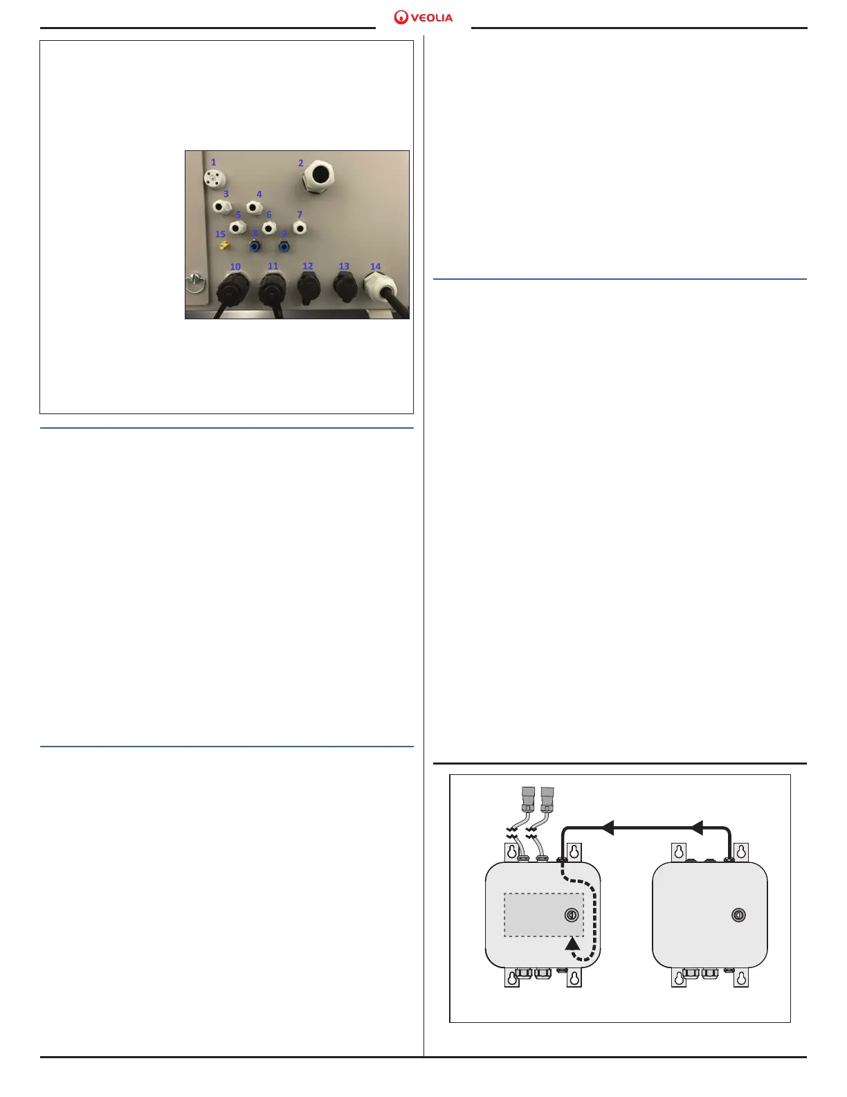
• All connections to the Analyzer will be connected
from the bottom of the enclosure. See Table 1 and
Figure 1 for the Port Names and Port Numbers.
Reference this table for all Port connections made
during installation.
Step 2: Select a location for the Analyzer
NOTE: If you have purchased the optional Mounting
Rack, refer to the Mounting Rack Installation
Instructions.
The Analyzer is designed to be mounted indoors on
an wall or support stand. For proper heat dissipation
and humidity control, ensure that 30.5 cm (12 in) is
available at the top and both sides of the Analyzer.
Allow 48.3 cm (19 in) clearance in front and below
the Analyzer for access to the interior and external
connections. When selecting the location, mount the
Analyzer so that the display screen is approximately
at eye-level. Mounting the Analyzer higher could lead
to potential serviceability and safety issues. For more
information, refer to “Chapter 3: Installation” and
“Appendix A: Analyzer Dimensions” in the Manual.
Avoid direct sunlight and extreme temperatures.
Operating at elevated temperatures greater than 40
°C (104 °F) prevents proper operation, and operating
at temperatures lower than 2 °C (35.6 °F), can cause
measurement errors.
Select and procure hardware for mounting the Analyzer
on a wall (M8 (qty 4), length variable) or instrument
rack (M6x12 (qty 4)), if using optional Mounting Rack),
hardware must be able to support four times the
weight of the unit [220 kg (485 lb)]. There are four
mounting brackets on the Analyzer; two on the top and
two on the bottom. The Analyzer must be mounted in
place to remain stationary and prevent damage to the
hardware.
Step 3: Install any Optional I/O or Carrier Gas
Accessories
The Communication Box, Air Box, and/or the Air
Scrubber are all purchasable accessories. Install any
accessories near the Analyzer, either wall mounted
or attached to an instrument rack. The optional
accessories must be installed within 150 cm (59 in)
of the Analyzer due to cable and tubing lengths. Do
not allow any tubes, cables, or wires to bend sharply.
Use appropriate weight bearing mounting hardware;
either M8x20 (qty 4) if using the optional Mounting
Rack or M8 (qty 4) for mounting to the wall. If mounting
to a wall, select an appropriate screw length for the
wall condition. Power should not be connected to
the Analyzer or any Accessories yet! For more
information, consult the Manual.
•
Afterwards, install the Customer I/O wiring
connections through the bottom of the
Communication Box enclosure. For more
information, consult the Manual.
• If using, install the Air Box and Air Scrubber.
The Air Box receives 24V DC power from the
Communication Box. The Air Box power wires
must be connected to the Communication Box.
The Air Scrubber Housing must be prepared. For
more information, consult the Manual.
Table 1. Analyzer Connections (all “Port” references)
1. Enclosure Drain
2. Sample Waste Outlet (Gravity Drain)
3. Dilution / Rinsing Water
4. Acid Supply Inlet
5. Calibration, Single Measurement, and Check Standard
Inlet
6. Sample Inlet 2
7. Sample Inlet 1
8. Carrier Gas
Outlet
9. Carrier Gas Inlet
10. Ethernet Port
11. No Connection
12. Analog Channel
(12-Pin
Connection)
13. Binary/Digital
Channel (12-Pin
Connection)
14. Power Supply Cord
15. No Connection
Figure 1. Connections/Ports (view from
below)
Figure 2. Communication Box and Air Box wiring
Air Box Power Wire Bundle
Port 13Port 12
Communication
Box
Air Box

 Loading...