4
© 2023 Veolia. All Rights Reserved. Sievers TOC-R3 Analyzer Installation Guide DQS 95000-01 EN Rev. A
*Sievers is a trademark of Veolia and may be registered in one or more countries.
Step 3 — continued...
Connect the Air Box Power
Wires
Route the ±24 V power wires
from the top of the Air Box to
the open port on the top of the
Communication Box. See Figure
2 on page 3. Open the
Communication Box door and
gently pull in any excess cable
length into the enclosure. Do not
allow the wires to bend sharply.
Connect the wires to the power
rail inside the Communication Box
next to the I/O Terminal Block. See
Figure 3.
Prepare the Air Scrubber
Housing
1. Carefully open the bottom
knurled cap (without tubing
ports) to reveal the inside of the Air Scrubber
Housing. The central tube comes pre-installed with
an Activated Carbon Cartridge.
2. Remove the Filter Ring.
3.
4. Reinstall the Filter Ring to seal the outer tube and
contain the Soda Lime granules.
5.
6. Slot the prepared Air Scrubber Housing into the
mounting brackets so that the Inlet and Outlet
ports are oriented on top of the Housing.
Connect the Communication Box to the Analyzer
NOTE: If using the Air Box, ensure the Air Box power
wiring connections have been completed prior to
connecting the Communication Box to the Analyzer.
1. Connect the Right Cable Connector (12-pin
connector on top of the Communication Box) to
Port 13 on the bottom of the Analyzer enclosure.
2. Next, connect the Left Cable Connector (12-pin
connector on top of the Communication Box) to
Port 12 on the bottom of the Analyzer enclosure.
See Figure 2 on page 3.
NOTE: The Right Cable Connector (Port 13) carries
power to the Communication Box power rail from the
Analyzer. See Figure 2 on page 3.
Step 4: Connect the Compressed Gas Source
The Analyzer requires low-CO gas as
and Accessories purchased, the compressed gas
connection, ensure there is an appropriate Pressure
Regulator [maximum of 100 kPa (1 Bar, 14.5 psig)]
installed nearby as well a dedicated Shut-o Valve.
The Analyzer Carrier Gas Inlet (Port 9) uses 6mm
OD, 4mm ID tubing. Cut the Carrier Gas Tubing with
a tubing cutter to length for your environment and
If using Nitrogen:
Connect the Nitrogen source Carrier Gas Line to the
Analyzer Carrier Gas Inlet (Port 9).
If using Zero/Synthetic Air:
Connect the Zero/Synthetic Air source Carrier Gas
Line to the Analyzer Carrier Gas Inlet (Port 9).
If using Plant Instrument Air (ANSI/ISA 7.0.01):
1. Connect the compressed Plant Instrument Air
source to the Air Scrubber Inlet (central port on
top of Air Scrubber Housing). Both the Analyzer
and Air Scrubber connection ports use 6 mm OD
tubing.
2.
top of Air Scrubber Housing) tubing to the Analyzer
Carrier Gas Inlet (Port 9).
If using Air Box Accessory:
NOTE: The Air Box has its
own Pressure Regulator
inside the enclosure.
1. Open the Air Box door.
2. Route the Carrier Gas
Tubing into the bottom
of the Air Box enclosure
through the hole shown.
See Figure 4.
3. Install the Carrier Gas
Tubing to the Outlet (left side) of the internal
Pressure Regulator.
4. Install the other end of the Carrier Gas Tubing to
the Air Scrubber Inlet (central port on top of Air
Scrubber Housing).
5.
top of Air Scrubber Housing) Carrier Gas Tubing to
the Analyzer Carrier Gas Inlet (Port 9).
Step 5: Connect the Waste Line
Locate the Waste Tubing [18] in the Shipping Kit. See
"Table 3. Shipping List" on page 9. Important!
The Analyzer requires a gravity drain with little to
no back pressure [less than 7 kPa (0.07 Bar, 1 psig)].
1. Open the Analyzer door and
locate the Gas Cooler Unit Drain
T-Fitting in the bottom right
compartment of the Analyzer.
2. Route the Waste Tubing up into
the Analyzer through Port 2. This
Figure 5.
3. Connect the Waste Tubing [18] to
the barb on the Gas Cooler Drain
T-Fitting. Ensure that the tubing
is fully inserted on the barb. See
Figure 5 and Figure 6 on page
5.
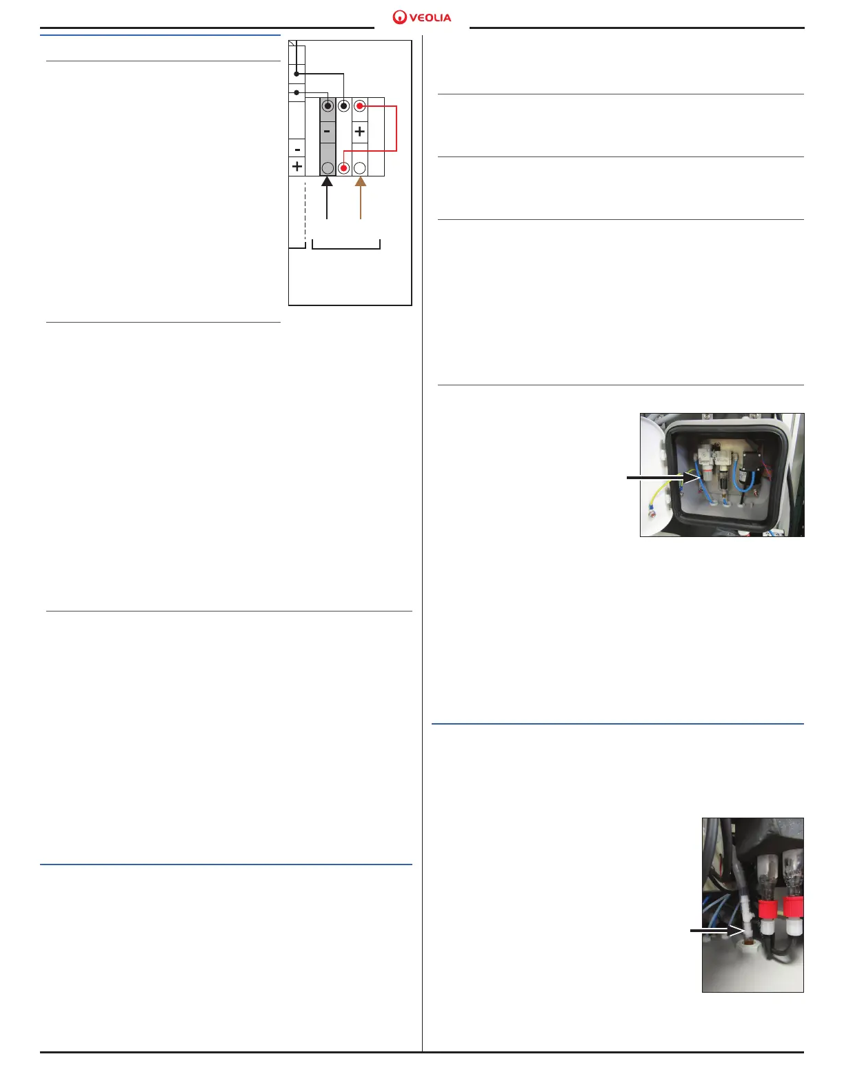
Figure 3.
Not Used
1 2 3 4 5 6 7 8 9 10
14 14 14 14
11 11 11 11
12 12 12 12
11 12 13 14 15
16
Option: From
Air Box Accessory,
Customer
connection.
01 02 03 04 05 06 14 15 16 17 12 13 14 15 16 17
Analog Output
(Connects to
Sensor Board)
0/4 - 20 mA Max. Load
V: 250 VAC
I: 5 A
V: 24 VAC, I: 2 A
0 - level: DC 0... 5 V
1 - level: DC 18... 30 V
Digital Output
(Connects to Digital I/O Board)
Indicates
Connection
on Circuit
Board
-24V
+24V
-24V
+24V
BLK BRN
Digital Input
Signal Strength by I/O Type
Lower terminal I/O Connections made by Customer
Upper terminal wires connected at the factory
NO NO NO NO
NC NC NC NC
Detail:
Air Box Power
Connections on
Communication Box
I/O Terminal Block
Figure 4. Air Box Carrier Gas
Tubing
Figure 5. Connect
the Waste Tubing
[18]

 Loading...