5
© 2023 Veolia. All Rights Reserved. Sievers TOC-R3 Analyzer Installation Guide DQS 95000-01 EN Rev. A
*Sievers is a trademark of Veolia and may be registered in one or more countries.
Step 5 — continued...
4. Route the other end of the Waste Tubing [18] into
Analyzer.
Step 6: Connect the Sample Line(s)
The Analyzer has up to two Sample Inlets for analysis.
The Sample Inlet Tubing (4 mm OD, 2 mm ID) for each
Sample Inlet (Port 7 and Port 6) comes pre-installed
from the factory. Determine the Sampling method
you will be using and install the Sample Line(s) to the
should be disabled until the Analyzer is ready to begin
analysis. Sample ow should remain OFF at this
time!
Connecting the Analyzer to a Sample Point
If connecting the Analyzer directly to a Sample Point,
sample pressure is within 0-20 kPa (0-0.2 Bar, 0-2.9
psig) and the Sample Point is within 2 m (6.5 ft) of
the Analyzer. This distance cannot be extended.
Connect the Sample Inlet Tubing to the Sample Point
connection.
Installing the Particulate Sampler, Optional
The Particulate Sampler is a purchasable option
Particulate Sampler to a Sample Point within 2 m
of the Analyzer. NOTE: This accessory uses Metric
Standard connections. The Inlet and Outlet PVC
for your environment. Once connected to your
environment, insert the Sample Inlet Tubing from the
Analyzer into the Particulate Sampler Assembly port.
US gal/min), the sample pressure at the system
is maximum of 20 kPa (0.2 Bar, 2.9 psig), and the
more information, consult the Manual.
Step 7: Install the Acid
The Analyzer uses a low-concentration Acid as a
reagent during analysis. The Acid type is based on
sample considerations. The Acid tubing needs to be
attached to the Acid Pump and the Acid needs to be
prepared. For more information, consult the Manual.
Connect the Acid Pump Tubing
Locate the Acid Pump and Acid
Tubing inside the right side
compartment in the Analyzer. The
Acid lines must be connected on
the Inlet and Outlet of the Acid
Pump. Connect the long Acid line
(that routes to the outside of the
Analyzer) to the Inlet, central port
on the Acid Pump. Connect the other, shorter Acid line
the tubing is tightly secured by gently pulling back on
it. See Figure 6 and Figure 7.
Prepare the Acid
Important! Always follow the SDS guidelines
for preparation, handling, and disposal of
Acid.
Prepare the Acid according to the manufacturer’s
instructions and the SDS in an appropriately labeled
carboy (both Acid and Acid Carboy are customer
supplied). Safely store the prepared Acid Carboy near
the Analyzer. The Analyzer Acid Line (Port 4) comes
pre-installed from the factory. Place the loose end of
the Acid Tubing into the prepared carboy. Ensure that
the tubing reaches the bottom of the carboy. For more
information, consult the Manual.
Step 8: Install the Dilution Water, Optional
Dilution Water Carboy with appropriate Dilution Water.
Safely store the prepared Dilution Water Carboy near
the Analyzer. The Dilution Water Line (Port 3) comes
pre-installed from the factory. Place the loose end of
the Dilution Water Tubing into the prepared carboy.
Ensure the tubing reaches the bottom of the carboy.
Step 9: Prepare the Furnace
Locate items [2] through [17] in the Shipping Kit. See
"Table 3. Shipping List" on page 9.
Access the Furnace
1. Remove the Furnace Access
Cover from the bottom of the
Analyzer enclosure. Release
the four captive screws
anticlockwise. Set the Cover
aside somewhere safe.
2. Locate the Furnace in the left
side compartment. See Figure
6.
3. From the top left corner of the Furnace, disconnect
the Wing Screw securing the Furnace in its upright
position. Do not lose this hardware!
Caution! Do not touch the hinge! Pinch Point!
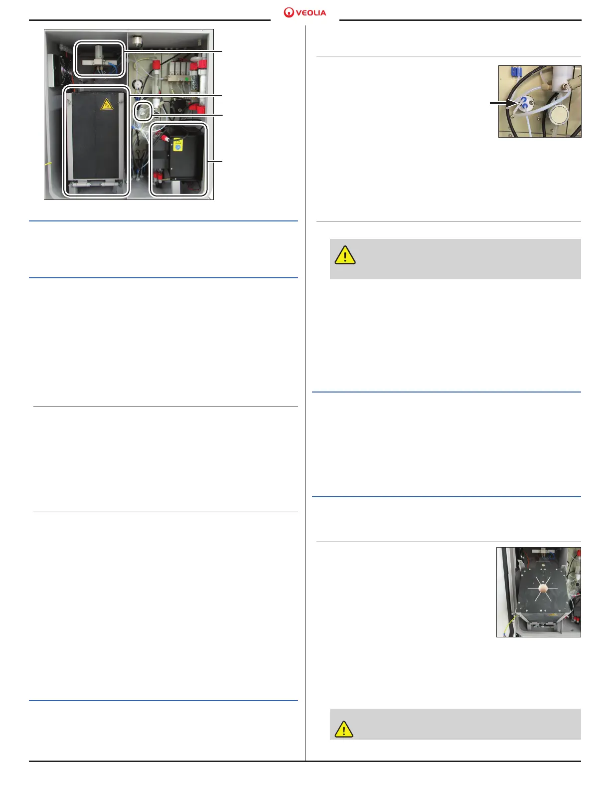
Figure 6. Analyzer Locations
Injection Block
Furnace
Acid Pump
Gas Cooler
Unit
Figure 7. Connect
Acid Pump Tubing
Figure 8. Tilt the
Furnace

 Loading...