8
© 2023 Veolia. All Rights Reserved. Sievers TOC-R3 Analyzer Installation Guide DQS 95000-01 EN Rev. A
*Sievers is a trademark of Veolia and may be registered in one or more countries.
Step 11: Set the Local Analyzer Settings
Navigate to the following: Menu → General. From
this screen you can set the local Analyzer settings.
Select the buttons below to adjust any of the following
settings.
• System Settings: Set the Language, Dark Mode,
Name(s), if desired.
• Time/Date Settings: Set the local Time and Date.
NOTE: This will require a system reboot.
• Ethernet: Set up the Ethernet Connection, if using.
For more information, consult the Manual. (Ethernet
cable is Customer provided)
Step 12: Perform Initial Analyzer Diagnostics
From the Touchscreen, select the Menu button (or use
Menu
screen).
Unlock the Analyzer
Unlock the Analyzer by selecting the Lock Icon in the
bottom left corner and inputting the default Machine
PIN “1111”. This pin can be changed at a later time.
For more information, consult the Manual.
Check the Sensor Values
Navigate to the following: Menu → Service →
Sensors. Observe the values being displayed. Only
installation. See Table 2 on page 8.
Adjust the “Carrier Gas Flow In” to the Analyzer
From the external Pressure Regulator or Air Box
Pressure Regulator (depending on the Analyzer
Flow IN to the Analyzer to be 25 liters per hour (l/h).
Sensors screen displays 25 l/h.
NOTE: If using Air Box, turn the Air Box Pressure
Regulator
Exercise the Valves
Navigate to the following: Menu → Service → Valve
Control. Select each valve to Open and Close the
Open and Close each valve ve times.
NOTE: The Y8 Valve is not used and will not cycle
when exercised. The Y10 and Y11 Valves are
powered together.
Check the Pumps
Navigate to the following: Menu → Service → Pump
Control. Working one at a time, select the Start
button for GP1, GP2, and GP4
that the hardware initiates when started. Press the
Stop
ve seconds.
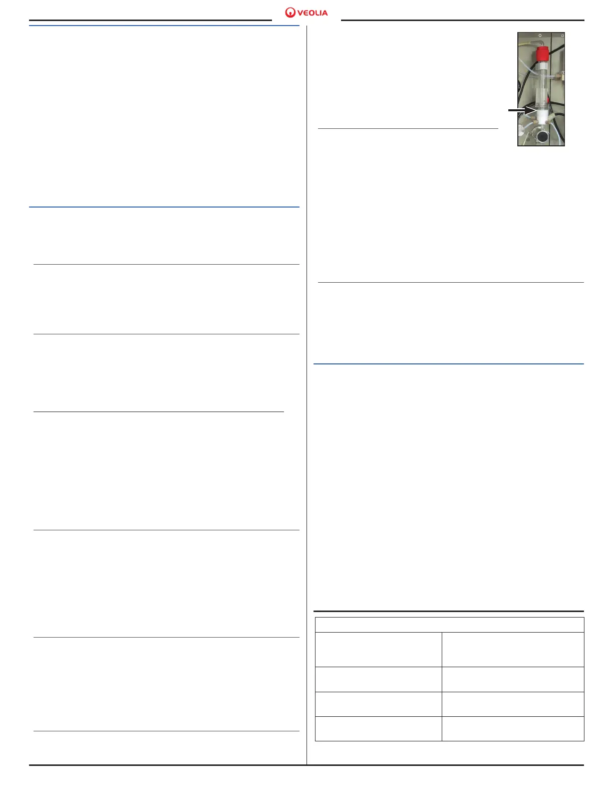
Prime the Acid Pump (GP3)
From the same screen, press the GP3 Pump button
about 50 times to fully prime the
Acid Pump. Each “Pump” pulse
will pull 200 µL of Acid into the
Acid Tubing. The Acid Pump is
considered primed once the Acid
of the Multi-function Sample Vessel
(MFSV). See Figure 17.
Clear any Analyzer Errors
The Analyzer will be displaying at
least one Error Code due to the
startup procedure. This is known and expected.
All Errors must be acknowledged by the User. To
view the current Error(s), either select the Error
button in the top right corner or the Error Icon (red
circle with a white “X”) in the bottom right corner to
view the System Information Screen. Select any
Functional Modules (Software, Electronics, Furnace,
or Sampling) with Error Codes displayed (starting with
“E1”) and Acknowledge them.
Test Input/Output Connections
If using the Communication Box for Input/Output
(I/O) control within the Analyzer, you must test that
these connections are working. For more information
consult the Manual.
Step 13: Installation Complete
The installation is now complete.
Figure 17. MFSV
Table 2. Sensor Values (Menu → Service → Sensors)
Carrier Gas Flow In —
should display ± 5 l/h to
“Carrier Gas Flow Out” value.
Carrier Gas Flow Out — should
display ± 5 l/h to “Carrier Gas
Flow In” value.
Pressure Reactor — should
display less than 50 mbar.
Temperature 2* — should be
between 30-40 °C.
Furnace Temperature —
should display 1200 °C.
Gas Cooler — should
display 5 °C.
Gas Cooler Environment —
should be between 30-40 °C.
*Temperature 1 Sensor is not used.

 Loading...