7
© 2023 Veolia. All Rights Reserved. Sievers TOC-R3 Analyzer Installation Guide DQS 95000-01 EN Rev. A
*Sievers is a trademark of Veolia and may be registered in one or more countries.
Step 9 — continued...
3. While holding the Injection Needle [15] in one
hand, carefully loosen the Compression Nut
[10A] with the other. Important! Do not let go of
the Injection Needle! It will fall into Furnace
Cartridge! See Figure 12.
4. Carefully slide the Injection Needle [15] up and
insert it into the Injection Block port. Ensure that
the Ferrule [14B] seats into the Injection Block
and then tighten the Injection Block Compression
tight.
5. Next, re-tighten the Compression Nut [10A] to be
See Figure 12 on page 6.
Install the Furnace Foot Assembly
Locate items [12], [13], [16], and three of item [17].
1. Temporarily disconnect the Transfer Tube from the
Furnace Foot Assembly [12]. It will be reattached
in a later step.
2. Insert the small Ceramic
Disk [16] into the center of
the Furnace Foot Assembly
[12]. Ensure the Disk is laying
Assembly [12]. Important!
Failure to install this correctly
will result in hardware failure!
See Figure 13.
3. Orient the Furnace Foot Assembly [12] so that the
Transfer Tube Port is on the right side.
4. Working from below through
the Furnace Access Port,
gently push the Furnace Foot
Assembly [12] on to the bottom
of the Furnace Sleeve [2]
extending out from below the
Furnace. Ensure the Transfer
Tube Port is oriented at a
45° angle between the Gas
Cooler Unit and the front of the
Analyzer. See Figure 14.
• NOTE: If the desired angle is not achieved on
[12] anticlockwise until the desired position is
obtained. Do not rotate clockwise or it will
loosen the ttings inside the Furnace Foot
Assembly [12] and risk
hardware failure!
5. Working one at a time, carefully
install the three Furnace Foot
Z-Brackets [13] to the bottom
of the Furnace using the three
Thumb Screws [17].
6. Rotate the Furnace Foot Z-Brackets [13] to slot
and clamp onto the Furnace Foot Assembly [12]
groove. Tighten the three Thumb Screws [17] to be
Figure 14 and Figure 15.
NOTE:
area.
7. Working from the right side compartment into the
left side compartment inside the Analyzer, pull the
Transfer Tube through the lower opening toward
the Furnace Foot Assembly [12].
8. Reconnect the Transfer Tube to the Furnace Foot
Assembly [12].
9. Set the loose end of the Transfer Tube next to the
Gas Cooler Unit in the right side compartment of
the Analyzer. It will be connected in a later step.
Do not connect it to the Analyzer. Leave it
open to atmosphere. Failure to do this may
result in hardware failure in the future due to
contaminants entering the system.
10. Reinstall the Furnace Access Cover.
Step 10: Connecting to a Power Supply
Connect power to the Analyzer in accordance with
local regulations and facility guidelines. A qualied
electrician must perform all electrical installation
activities. For more information, consult the Manual.
Ensure all power connections are made with the
POWER OFF.
• Power ON the Analyzer by turning the Rotary
Power Switch on the right side of the Analyzer to
the vertical, ON position.
•
hardware have power before continuing. With the
Analyzer door open, observe the Gas Cooler Unit
in the lower right side compartment of the Analyzer.
The right, Red LED will illuminate while it is cooling
down to temperature. The left, Green LED will
illuminate once the system is at temperature (about
10 minutes). See Figure 6 on page 5 and
Figure 16.
Caution! Very Hot temperatures! Do not
touch the Furnace, Furnace Head Assembly,
or Furnace Foot Assembly without proper
PPE.
Important! Allow the Analyzer to run for two hours
before continuing to the next step. The Furnace must
heat up to temperature (1200
°C, 2192 °F) and be allowed
manufacturing residues.
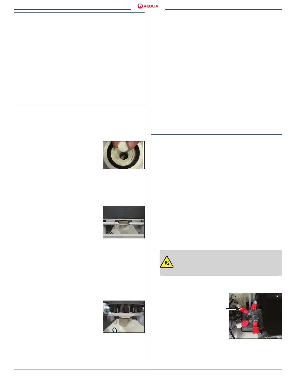
After two hours, connect the
loose end of the Transfer
Tube to the Gas Cooler
Unit. See Figure 16. Ensure
to use proper PPE while
working inside the Analyzer.
The Analyzer system is now
closed. Close the Analyzer
door.
Figure 13.
Ceramic
Disk [16]
Figure 14. Furnace
Foot Assembly [12]
groove and correct
orientation
Figure 15. Furnace
Foot Assembly
Z-Brackets
Figure 16. Gas Cooler Unit
and LED (View from above)

 Loading...