6
© 2023 Veolia. All Rights Reserved. Sievers TOC-R3 Analyzer Installation Guide DQS 95000-01 EN Rev. A
*Sievers is a trademark of Veolia and may be registered in one or more countries.
Step 9 — continued...
4. Carefully tilt the Furnace forward 45° on its hinge.
See Figure 8.
Prepare the Furnace
Locate items [2], [8], [9], and three of the item [17].
1. Slide the Isoplan High Temperature Gasket [8]
(Large ID) on to the Furnace Sleeve [2] until it is
2. Insert the Furnace Sleeve [2] (and attached
Gasket) into the central hole of the Furnace and
with the Furnace surface.
3. Working one at a time, install
the three Furnace Head
Z-Brackets [9] to the top of
the Furnace using the three
Thumb Screws [17]. These
brackets will be tightened in a
later step. Attach them to the
Furnace but keep them loose.
See Figure 9.
Prepare and install the Furnace Cartridge
Locate items [3], [4], [5], and [11].
1. Insert the Support Plate [5] into the Furnace
Cartridge [3].
2. Using a small funnel, carefully pour the Ceramic
Balls Set [4] into the Furnace Cartridge [3] in the
following order:
• Packet 1 (I); Bottom layer, (Large beads, larger
amount in bag)
• Packet 2 (II); Middle layer, (Small beads)
• Packet 3 (III); Top layer, (Large beads, smaller
amount in bag)
3.
Furnace Sleeve [2] in the Furnace.
4. Install the O-Ring [11] in between the Furnace
Sleeve [2] and the Furnace Cartridge [3]. See
Figure 9.
Prepare the Furnace Head Assembly
Locate items [6], [7], [10], [14], and [15].
1. Slide the Isoplan High Temperature Gasket [7]
(small ID) over the Furnace Head Compression
Fitting [10] attached to the Furnace Head Cover
Furnace Head Cover [6]. See Figure 10.
2. Carefully loosen the Compression Nut [10A] but
do not remove it.
3. Insert the Injection Needle [15] through the
loosened Compression Nut [10A] and Furnace
Head Cover [6].
• NOTE: If needed, you can remove the Furnace
Head Compression Fitting [10] and individually
slide the Nut and Ferrules [10A through 10D] on to
the Injection Needle [15]. Be careful to not lose
any pieces! Ensure the ferrules are installed using
the correct orientation.
4. Next, slide the Injection
Block Compression
Fitting [14] on to the end
of the Injection Needle
[15]. Ensure the ferrule
[14B] is oriented correctly.
5. Push the Injection Needle
[15] down through the
Furnace Head Cover [6]
until there is about 8 cm
(3 in) remaining above
the Furnace Head Cover
[6].
6. Tighten the Compression
Nut [10A] on to the
Furnace Head Cover [6]
will secure the Injection
Needle [15] to the
Furnace Head Cover [6].
7. These parts assembled
together are now
considered the “Furnace Head Assembly”.
Install the Furnace Head Assembly
Insert the Furnace Head Assembly into the center hole
on top of the Furnace (covering the Furnace Cartridge
[3] and O-Ring [11]). Important! Ensure the O-ring
[11] is correctly seated before installing Furnace
Head Assembly!
Tighten the Furnace Head Z-Brackets
Rotate the Furnace Head Z-Brackets [9] to clamp
down on the Furnace Head
Assembly and tighten the three
tight. Important! Ensure that the
metal Z-Brackets [9] only touch
the High Temperature Gasket
[7]! If needed, slide the slotted
Z-Brackets farther away from the
center tting before tightening
the Thumb Screws [17]. See
Figure 11.
Insert the Injection Needle into the Injection Block
1. Carefully tilt the Furnace back into its vertical,
upright position.
2. Secure it in place
using the Wing
Screw that was
removed earlier.
Figure 9. Z-Brackets,
Thumb Screws, and
O-Ring
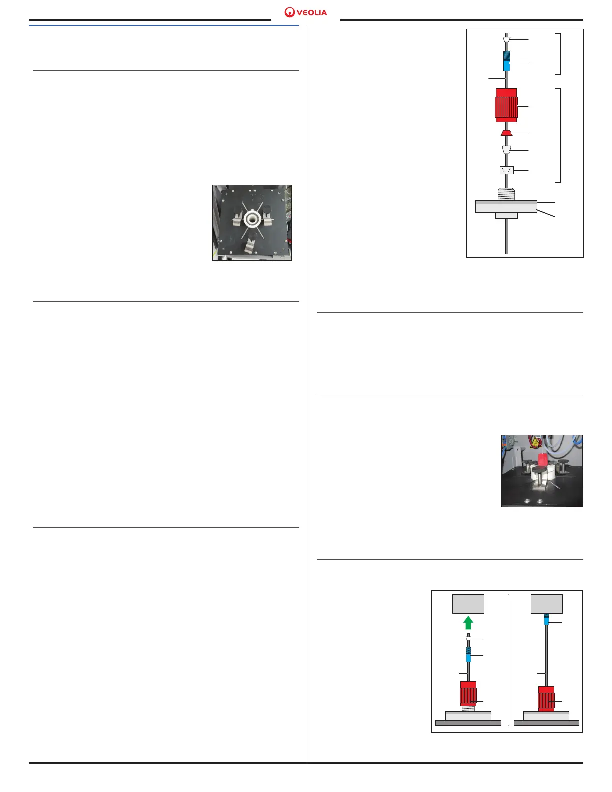
Figure 10.
[15]
[14A]
[14B]
[7]
[10]
[6]
[10D]
[10C]
[10B]
[10A]
[14]
Exploded view of
Furnace Head Assembly
Figure 11. Tighten
Z-Brackets and
Thumb Screws
Figure 12.
[15]
[14A]
[14B]
[10A]
[15]
[14A]
[10A]
Connect Injection Needle
to Injection Block

 Loading...