24
10 Tub Vent Arrangement
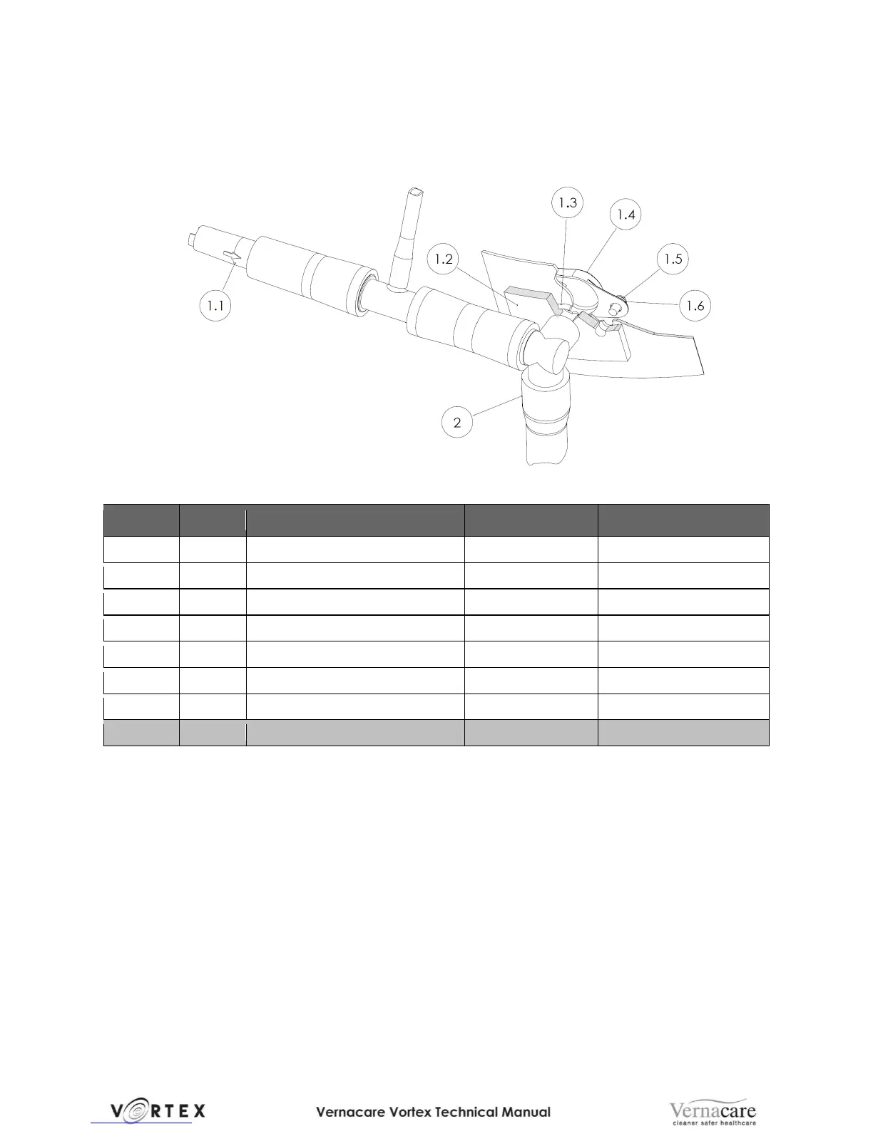
Figure 8 – Vent Assembly
Detail of Vent Connection
Situated at the front top right hand side of the hopper is a vent connector (2) which allows
the foul air which is displaced whilst water is filling the hopper, to be vented into the drain.
The vent connector is fitted with a non - return valve (1) (push fit into connector with the
arrow on its body pointing into the connector). This valve prevents air from being expelled
to atmosphere during water filling but allows air to be drawn into the hopper during the
drain cycle when a vacuum would otherwise be created.
The connector is secured to the hopper via two M4 screws (5) and two nylon washers (4),
to prevent leakage an O-ring (3) is used to seal the connector to the hopper and is
located in a groove on the inner face of the connector.