Do you have a question about the Vernacare VORTEX AIR and is the answer not in the manual?
Details European standards and common specifications for product compliance.
Lists product codes for various Vortex Air models.
Outlines the authorized personnel for the technical file.
Provides details on the terms, conditions, and contact information for product warranty.
Information regarding the availability and nature of service contracts for the product.
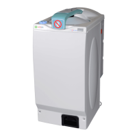
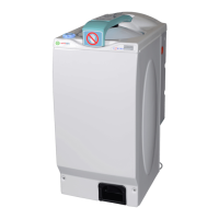
Provides a general description of the Vortex Air disposal unit's functionality and capacity.
Shows the physical dimensions and required clearance space for machine installation.
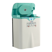
Provides an exploded view and list of key components and assemblies for familiarisation.
Details power requirements, circuit protection, and electrical safety precautions.
Details specifications for AC motor, inverter, pump, water, and drainage requirements.
Provides guidance on positioning, securing, and required clearances for installation.
Details the specific requirements for connecting the water supply and drainage systems.
Lists the environmental conditions (altitude, temp, humidity, voltage) for safe operation.
Step-by-step instructions for operating the macerator and its automatic lid.
Guidelines on proper usage and prohibited actions to ensure safe operation.
Explains various on-screen icons and error messages displayed by the machine.
Illustrates the timing sequence of components for different operational modes.
Illustrates the timing sequence of components for the Eco operational mode.
Illustrates the timing sequence of components for the Standard operational mode.
Illustrates the timing sequence of components for the Heavy Duty operational mode.
Provides a diagram of the Printed Circuit Board (PCB) with reference numbers for components.
Provides a schematic illustrating the connections and types of sensors used in the machine.
Shows the wiring configuration for the AC motor, illustrating its connection to the inverter.
Details the electrical enclosure, showing the mains supply, inverter, and power supply connections.
Instructions on how to access and navigate the machine's engineering mode.
Detailed explanation of each feature available within the machine's engineering mode.
Provides daily cleaning procedures and maintenance guidance for the Vortex Air.
Details the electrical assembly, including the PSU and inverter unit components.
Describes the diaphragm assembly, also known as the drain valve, and its function.
Explains the safety switch assembly, a secondary mechanism to prevent motor running with an open lid.
Details the rotary lid actuator responsible for opening and closing the lid.
Describes the lid assembly, including the inflatable seal and other key components.
Explains the pneumatics assembly responsible for air distribution to drain and lid seals.
Details the AC motor assembly, which drives the cutter blades and ensures watertightness.
Describes the interlock assembly that locks the lid in place when closed.
Explains the water tank, its capacity, and its role in the macerator's operation.
Addresses symptoms and checks for when the machine appears to have no power.
Covers errors preventing the cycle from starting, such as low water or blocked drains.
Addresses issues where the motor is not working or maceration is ineffective.
Details symptoms and checks for when the water pump is not working or lacks capacity.
Covers problems related to the lid not opening, closing, or only partly operating.
Addresses different types of water leaks and their potential causes and checks.
Covers issues with deodoriser dispensing, hopper emptying, and diaphragm inflation.
| Category | Medical Equipment |
|---|---|
| Type | Air Disinfection Unit |
| Air Changes Per Hour (ACH) | 6 ACH |
| Power Supply | 220-240V, 50/60Hz |
| Weight | 15 kg |
| Filter Life | 12 months |
| UV-C Lamp Life | 9000 hours |
| Technology | UV-C |