EasyManua.ls Logo

Vernacare VORTEX AIR - Assembly Diagrams and Descriptions; Electrical Assembly

Default Icon
43 pages
Print Icon
To Next Page IconTo Next Page
To Previous Page IconTo Previous Page
Loading...
Page | 25
VORTEX AIR Technical Manual
Revision 6- Issued by N. Shields 24/08/2023
5. Assembly Diagrams & Descriptions
5.1. Electrical Assembly
How it Works
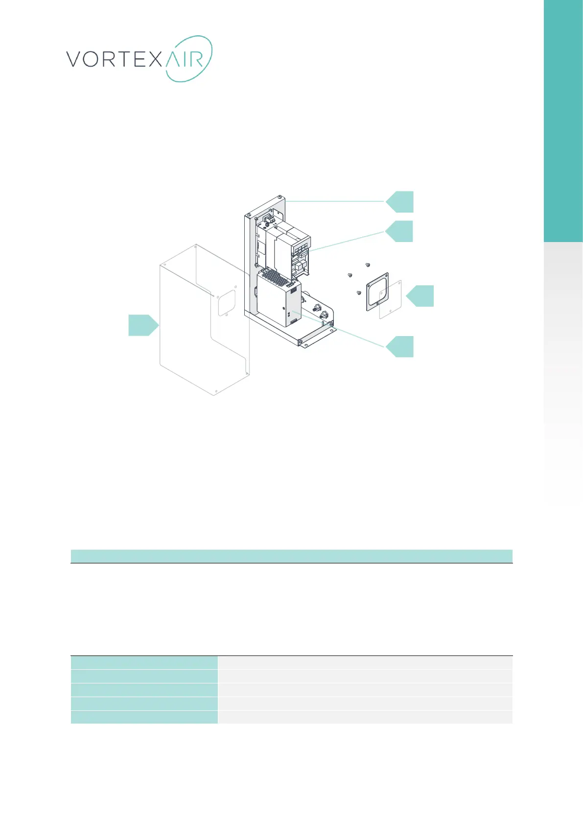
This is often referred to as the ‘PSU’ unit. The electrical assembly consists of both the power
supply and inverter unit. The power supply distributes incoming mains power to the PCB board
and machine components. The inverter is used to control the AC motor as well as monitoring the
load. This system can detect ‘Blocked Blade’ errors when a user has either overloaded or put a
foreign object into the machine.
1
Electrical Chassis
2
Mitsubishi Inverter Unit
3
Inverter Display Panel & Gasket
4
Power Supply
5
Electrical Chassis Cover Panel
5
1
3
4
2

Related product manuals