EasyManua.ls Logo

VERSATEK VX-MD4024 - Connecting the Vdsl;Adslx and POTS Interfaces

VERSATEK VX-MD4024
48 pages
Print Icon
To Next Page IconTo Next Page
To Previous Page IconTo Previous Page
Loading...
1 Installation of the VX-MD4024
1.2.6 Connecting the VDSL/ADSLx and POTS interfaces
The VX-MD4024 supports 24 ports VDSL2/ADSLx subscribers per box. Depending on your box,
there maybe two RJ21 50-pin female connectors on the front panel of the system. One for
VDSL/ADSLx line and the other for POTS interface.
To connect the subscriber lines, use cables with the RJ21 50-pin male connectors. When
installing, just plug the end of a cable with connector into the POTS or LINE interface female
connector on the front panel. The other end of the cable is generally tied to the MDF.
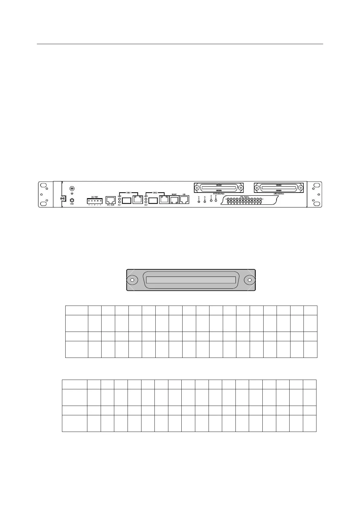
The following figure shows the Line/POTS port position of the system:
POTS port 24 1 LINE port 24 1
The pin assignment of Line/POTS interface is illustrated below (the numbers in the connector
figures below represent PIN numbers). Please be aware of the different style pin-assignment.
Line port 1~24:
125
2650
Pin No.
25
24
23
22
21
20
19
18
~
8
7
6
5
4
3
2
1
Port No.
X
Ring
23
Tip
23
Ring
21
Tip
21
Ring
19
Tip
19
Ring
18
~
~
Ring
7
Tip
7
Ring
5
Tip
5
Ring
3
Tip
3
Ring
1
Tip
1
Pin No.
50
49
48
47
46
45
44
43
~
33
32
31
30
29
28
27
26
Port No.
Ring
24
Tip
24
Ring
22
Tip
22
Ring
20
Tip
20
Ring
18
Tip
18
~
Tip
8
Ring
6
Tip
6
Ring
4
Tip
4
Ring
2
Tip
2
X
Figure 1-10 Pin Assignment of LINE Interface (VDSL2 30a, Horizontal Tip/Ring model)
Pin No.
25
24
23
22
21
20
19
18
~
8
7
6
5
4
3
2
1
Port No.
X
Tip
25
Tip
24
Tip
23
Tip
22
Tip
21
Tip
20
Tip
19
~
~
Tip
8
Tip
7
Tip
6
Tip
5
Tip
4
Tip
3
Tip
2
Tip
1
Pin No.
50
49
48
47
46
45
44
43
~
33
32
31
30
29
28
27
26
Port No.
X
Ring
25
Ring
24
Ring
23
Ring
22
Ring
21
Ring
20
Ring
19
~
Ring
8
Ring
7
Ring
6
Ring
5
Ring
4
Ring
3
Ring
2
Ring
1
Figure 1-11 Pin Assignment of LINE Interface (VDSL2 17a, Vertical Tip/Ring model)

Table of Contents