13VX-1700 Series (EXP Version) Service Manual
Receiver Alignment
RX IF COILS ALIGNMENT
Connect the RF Signal Generator to the ANT jack,
and connect the AF millivoltmeter to the EXT SP
jack.
Tune the radio to 19.900 MHz, CW mode.
Inject a 19.900 MHz signal from the RF Signal
Generator, then adjust the RF Signal Generator
output level to 0 dB.
Adjust T1012 on the MAIN Unit for maximum
indication on the AF millivoltmeter.
Transmitter Alignment
TX IF COILS ALIGNMENT
Connect the 50 Ohm Dummy Load to the ANT
jack.
Remove the coaxial plug from J1002 on the MAIN
Unit, then connect the RF millivoltmeter and 50
Ohm resistor to J1002.
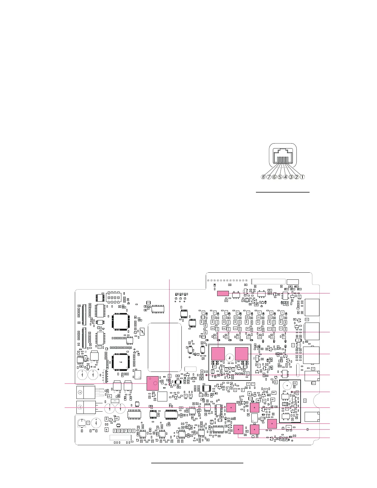
Connect the AF Generator to pin 4 of the MIC
jack.
Tune the radio to 7.500 MHz, USB mode.
Inject a 0.5 mVrms @1000 Hz audio signal from
the AF Generator.
Key the transmitter (connect pin 3 of the MIC jack
to GND), then adjust T1008, T1009, T1010, and
T1011 on the MAIN Unit in succession several
times for maximum indication on the RF milli-
voltmeter while transmitting.
MAIN UNIT ALIGNMENT POINTS
J1002
T1067
T1066
TP1039
T1010
T1008
T1009
T1010
X1003
PIN 4 OF Q1062
TP1048
T1012
MIC JACK PINOUT
 Loading...