21VX-1700 Series (EXP Version) Service Manual
Installation
Make sure that the transceiver off. Remove the
DC Power Cable, Microphone, and Antenna from
the transceiver.
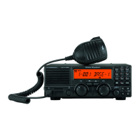
Referring to Figure 1, remove the four screws
from the side of the transceiver (two screws for
each side), along with four screws affixing the
bottom case; remove the bottom case.
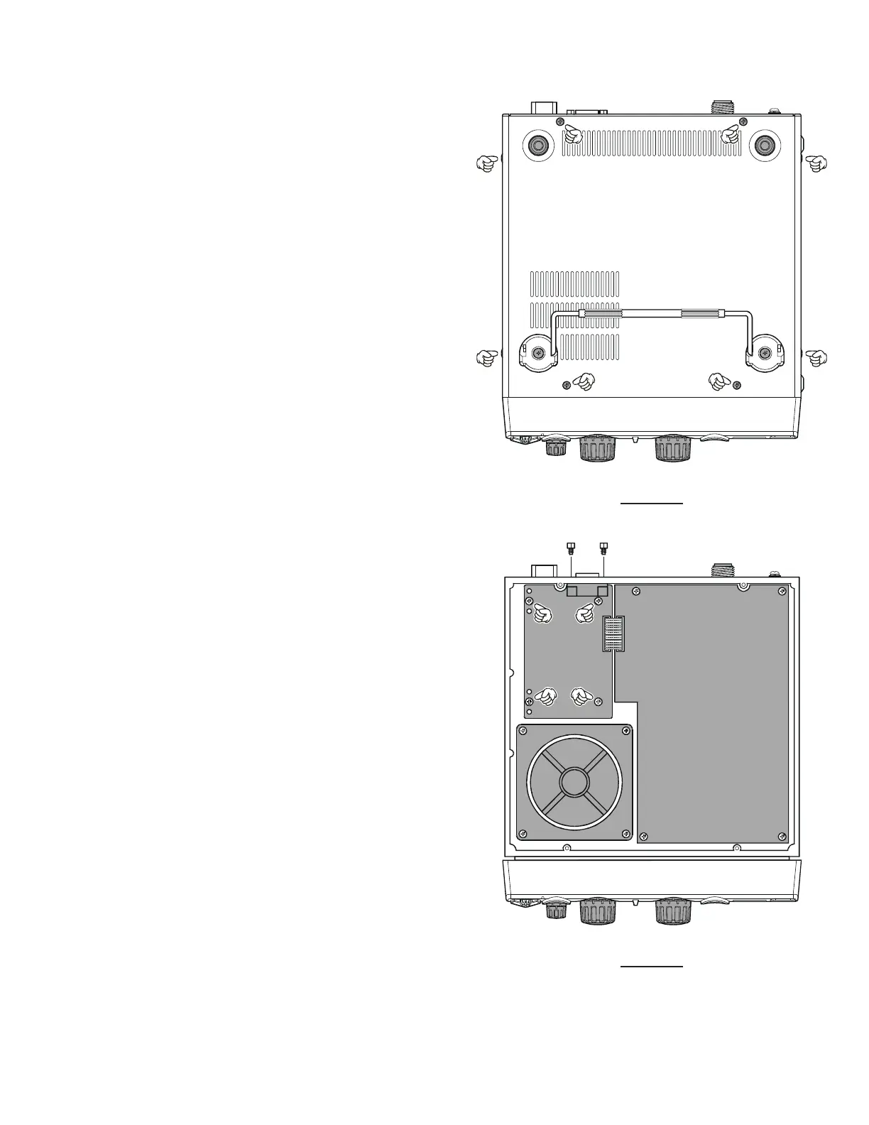
Referring to Figure 2, disconnect the 13-pin con-
nector from J4001 on the GPS-INTERFACE Unit,
remove the two HEX bolts which and four screws
affixing the GPS-INTERFACE Unit.
Remove the GPS-INTERFACE Unit from the
transceiver.
Install the ALE-1 Unit to the place where it has
the GPS-INTERFACE Unit.
Fix the ALE-1 Unit with two HEX bolts and four
screws.
Connect the 13-pin connector to J4001 on the
ALE-1 Unit.
Replace the bottom case with its eight screws.
Connect the DC Power Cable, Microphone, and
Antenna to the transceiver.
Programming
Connect the CT-62 Programming Cable between
computer’s 9-pin COM port and the transceiv-
er’s TUNER jack.
Press and hold in the
[
F
]
and
[
9
(
M/W
)]
keys while
turning the power on to enter the clone mode.
Execute the CE77 Programming Soft, then upload
the current programming data from the transceiv-
er via the “Upload” menu in the “Radio” param-
eter.
Click the left mouse button on the “Common”
parameter, then click the left mouse button on
the “Option” parameter to involve a pop-up win-
dow, select the “Option Board” item, and change
its setting to “ALE Unit.”
Click the left mouse button on the [OK] button
to close the pop-up window.
Program the ALE features.
Download the revised programming data to the
transceiver from the computer via the “Down-
load” menu in the “Radio” parameter.
Installation and programming are now complete.
Disconnect the CT-62 Programming Cable from
the transceiver’s TUNER jack.
ALE-1 Automatic Link Establishment Unit Installation
GPS-INTERFACE
Unit
MAIN Unit
J
4001
Cooling Fan
FIGURE 1
FIGURE 2
 Loading...