VX-2200
(
LTR
)
12
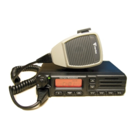
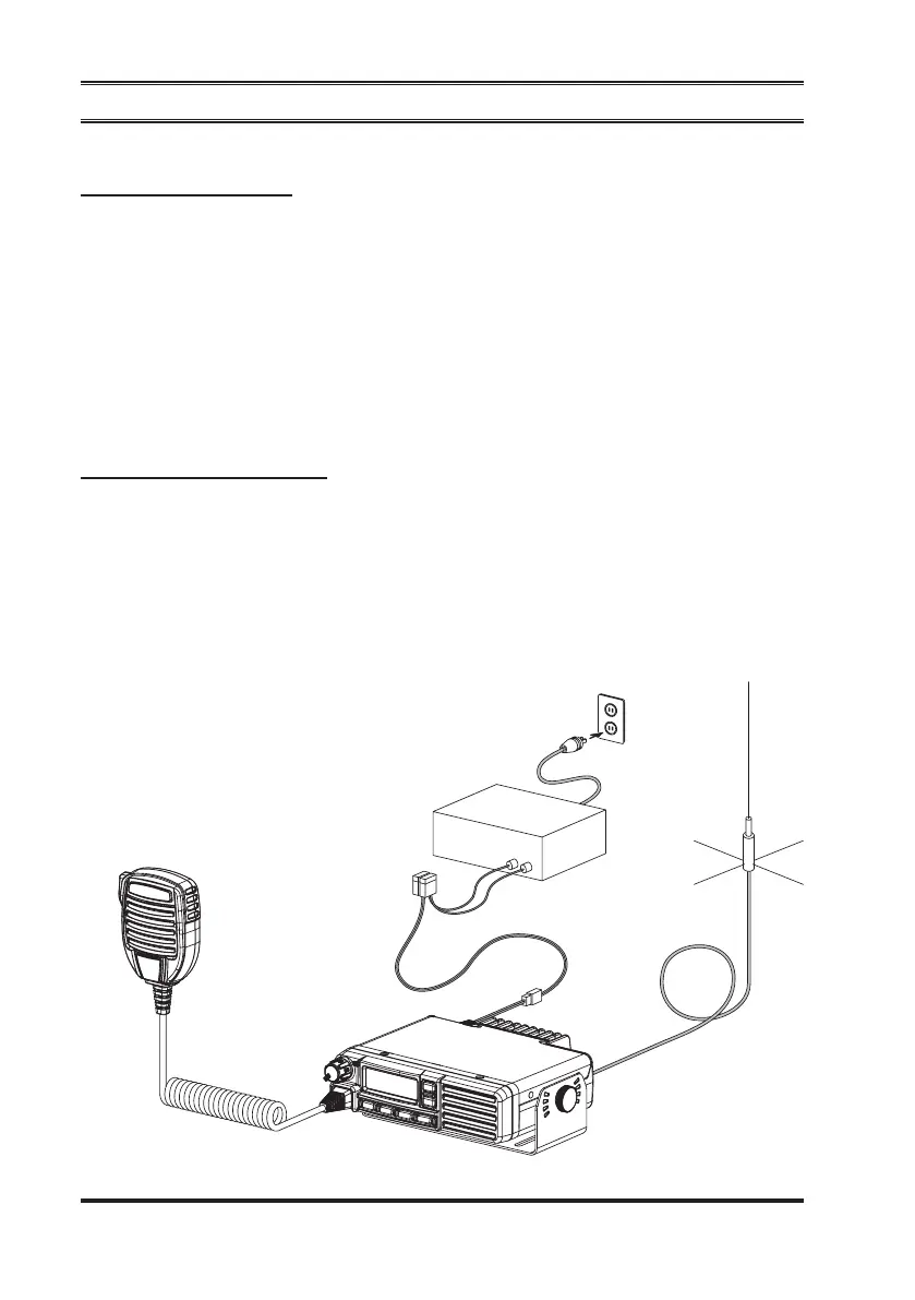
Base Station Installation
Power connection
Operation of the
VX-2200
(
LTR
)
transceiver from an AC line requires a power
supply capable of providing at least 15 Amps continuously at 13.6 Volts DC.
Please contact your dealer to select an optimal power supply that satisfy these re-
quirements.
Use the supplied DC power cable for making power connections to the power
supply. Connect the RED power cable lead to the POSITIVE
(
+
)
power supply
terminal, and connect the BLACK power cable lead to the NEGATIVE
(–)
power
supply terminal.
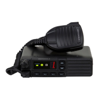
AntennA instAllAtion
When used the
VX-2200
(
LTR
)
transceiver as a base station, the antenna installa-
tion must comply with the following requirements in order to ensure optimal per-
formance and compliance with the RF energy exposure limits in the standards and
guidelines.
r
The antenna should be mounted outside the building on the roof or a tower if
at all possible.
installatiOn
RED: POSITIVE
(
+
)
Terminal
BLACK: NEGATIVE
(
–
)
terminal
AC Power Supply
(
13.6 V, 15 A
)
Antenna
 Loading...