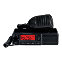
Page 8 VX-1700 OPERATING MANUAL
MOBILE MOUNTING
The optional MMB-89 Mobile Mounting Bracket allows
quick insertion and removal of the VX-1700 transceiver
from the vehicle. Complete installation instructions are
provided with the bracket.
Mobile Antenna Considerations
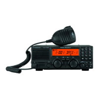
The VX-1700 transceiver is designed for use with any
antenna system providing a 50-Ohm resistive impedance
at the desired operating frequency. While minor excur-
sions from the 50-Ohm specification are of no conse-
quence, the power amplifier’s protection circuitry will
begin to reduce the power output if there is more than a
50% divergence from the specified impedance (less than
25 Ohms or greater than 100 Ohms, corresponding to a
Standing Wave Ratio (SWR) of 2.0:1). Compliance with
this specification critically depends on the range of fre-
quencies on which operation will take place, and the de-
sign of the antenna(s) in use.
If your mobile or marine operation requires wide frequency
coverage, the Yaesu YA-007FG or similar mobile whip
antenna may be used in conjunction with the Yaesu FC-
40 External Antenna Tuner. The FC-40 is designed to
accommodate a wide variety of whip impedances at the
operating frequency, converting these to the desired 50
ohm impedance via a sophisticated microprocessor-con-
trolled impedance matching circuit. The FC-40 and VX-
1700 provide memory of antenna matching settings suf-
ficient for all channels on Memory Bank 1. In marine ap-
plications, the FC-40 is also ideal for the use with a
“backstay” antenna or marine mobile whip.
The FC-40 should be located at or near the base of the
antenna, so as to minimize losses and stray radiation. The
short lead-in wire from the whip must be securely bonded
both to the FC-40 and the antenna (whip or wire), and the
FC-40 must be securely bonded to the vehicle or vessel
ground system, which will act as a counterpoise for the
FC-40 and antenna radiating element. Be sure to weath-
erproof all outdoor connections thoroughly, especially in
maritime environments.
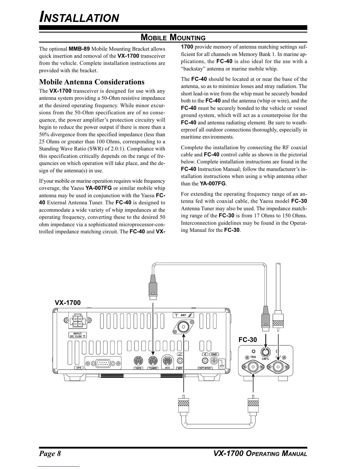
Complete the installation by connecting the RF coaxial
cable and FC-40 control cable as shown in the pictorial
below. Complete installation instructions are found in the
FC-40 Instruction Manual; follow the manufacturer’s in-
stallation instructions when using a whip antenna other
than the YA-007FG.
For extending the operating frequency range of an an-
tenna fed with coaxial cable, the Yaesu model FC-30
Antenna Tuner may also be used. The impedance match-
ing range of the FC-30 is from 17 Ohms to 150 Ohms.
Interconnection guidelines may be found in the Operat-
ing Manual for the FC-30.
VX-1700
FC-30
INSTALLATION