Page 15VX-1700 OPERATING MANUAL
OPERATION
If the station you are listening to should drift or other-
wise be unclear (the voice may sound too high-pitched
or too low-pitched), pressing the
[
P1
]
or
[
P3
]
key may
improve the sound of the incoming signal. The
[
P1
]
/
[
P3
]
key function does not affect your transmission
frequency; only the receive frequency is being ad-
justed. When the receiving frequency is higher than
displayed frequency, the “” icon will appear to the
right of the frequency display. Similarly, when the re-
ceiving frequency is lower than displayed frequency,
the “” icon will appear to the right of the frequency
display. Press and hold in both
[
P1
]
and
[
P3
]
keys for
one second to reset the offset.
If the LCD display is too bright, press the keypad’s
[
0
(
DIM
)]
key to reduce the display brightness. Press
the
[
0
(
DIM
)]
key again return to the LCD display to
nominal brightness level.
To turn the internal speaker (or external speaker, if
used) off, press the
[
P4
]
key. Press the
[
P4
]
key again
to restore the speaker audio.
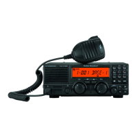
TRANSMISSION
For Voice transmission, close the PTT (Push To Talk)
switch on the microphone; the transmitter will now be
activated (note that the “ ” icon will be illuminated
on the LCD display). Hold the microphone about 1
inch (25 mm) from your mouth, and speak into the
front of the microphone in a normal voice level. Re-
lease the PTT switch to return to the receive mode
(the “ ” icon will be again illuminated, and the
“ ” icon will go out).
For CW (Morse Code telegraphy) in the A1A mode,
begin sending using your telegraph key or electronic
keyer. The VX-1700 will automatically be placed in
the transmit mode when you start to send, and will
revert to the receive mode when you stop sending. As
you send, a “Sidetone” audio generator allows you to
monitor your sending.
For Data transmission (including Morse Code teleg-
raphy using a TNC (Terminal Node Controller) and
keyboard, or similar computer-driven data transmis-
sion devices), transmit/receive control is exercised by
the software which accompanies the data transmission
equipment in use. See the User’s Manual for your ter-
minal equipment for operating instructions. Remem-
ber to follow the maximum power output guidelines
during continuous-duty operation such as RTTY (Ra-
dio Teletype) in the J2B mode. Adjust the TX Audio
level from the TNC for a maximum of 50 Watts of
power output (5 or 6 segments illuminated on the
Power Output Bar Graph) if long periods of continu-
ous transmission are anticipated.
Antenna Tuning Procedures
When the optional FC-30 or FC-40 External Antenna
Tuner is installed, it is activated on each channel auto-
matically.
If the “ ” icon appears at the upper right corner on the
LCD display while transmitting, the antenna system may
require retuning. Use the following procedure.
Be certain that all connections to the FC-30/-40 have
been properly made.
With the appropriate channel selected via the Main
Dial, press the keypad’s
[
3
(
TUNER
)]
key. The
“ ” icon on the LCD Display will blink, and
the VX-1700 will transmit for a short time. Thereaf-
ter, the transceiver will return to the receive mode, and
the “ ” icon will now be illuminated constantly.
The FC-30/-40’s microprocessor-based circuitry in-
cludes memory sufficient to retain 100 (for FC-30,
200 for FC-40) antenna tuning settings in memory.
This will greatly reduce frequency change time. If you
utilize more than 100 or 200 operating channels that
are widely removed in frequency, the new tuning set-
tings will be over-written on a first-in, first-out basis.
RECEPTION
Front Panel Locking
To prevent inadvertent changing of the channel fre-
quency or other front panel parameters, press the
[
P2
]
key on the front panel. All keys, and the Channel Se-
lector knob, will locked out of the operational com-
mand capability except for the POWER switch, the
[
DOWN
]
and
[
UP
]
buttons, and the
[
P2
]
key itself.
The “ ” icon will appear on the display.
Press the
[
P2
]
key again to release the front panel to
normal operation.