12
VX-920/-920E VHF series Service Manual
Alignment
Alignment Preparation & Precautions
A 50-Ohm RF Dummy Load and in-line wattmeter
must be connected to the main antenna jack in all
procedures that call for transmission, except where
specified otherwise. Correct alignment is not possi-
ble with an antenna.
After completing one step, read the following step
to determine whether the same test equipment will
be required. If not, remove the test equipment (ex-
cept dummy load and wattmeter, in connected) be-
fore proceeding.
Correct alignment requires that the ambient temper-
ature be the same as that of the transceiver and test
equipment, and that this temperature be held con-
stant between 68 and 86 °F (20 ~ 30 °C). When the
transceiver is brought into the shop from hot or cold
air, it should be allowed time to come to room tem-
perature before alignment.
Whenever possible, alignments should be made with
oscillator shields and circuit boards firmly affixed
in place. Also, the test equipment must be thorough-
ly warmed up before beginning.
Note: Signal levels in dB referred to in the align-
ment procedure are based on 0 dBm EMF = 1 mV.
Setup the test equipment as shown for transceiver
alignment, apply 7.5 V DC power to the transceiv-
er. Refer to the drawings above for Alignment
Points.
The transceiver must be programmed for use in the
intended system before alignment is attempted. The
RF parameters are loaded from the file during the
alignment process.
In order to facilitate alignment over the complete
switching range of the equipment it is recommend-
ed that the channel data in the transceiver is preset
as the chart below.
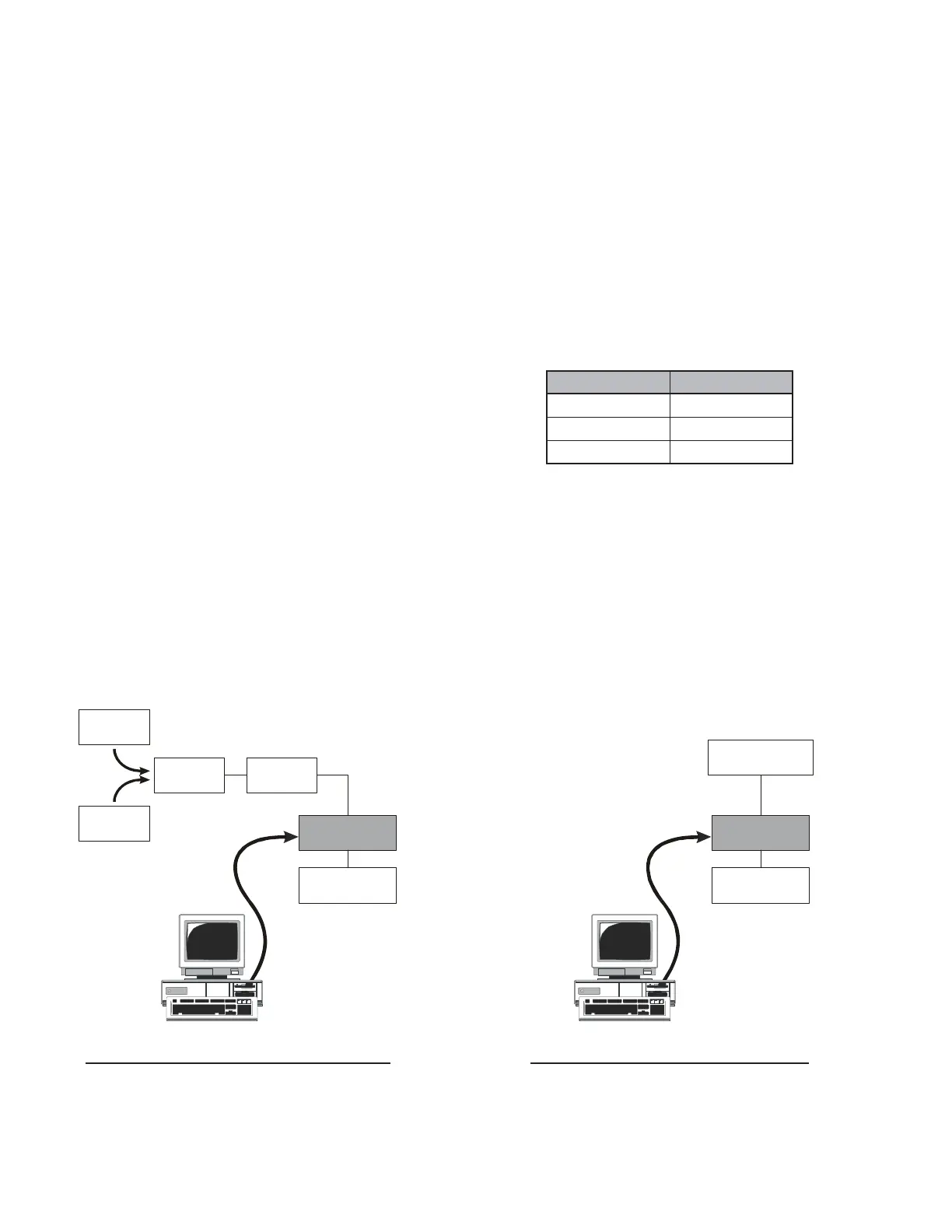
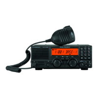
TRANSMITTER SECTION ALINGMENT SETUP RECEIVER SECTION ALINGMENT SETUP
The alignment mode is accessed by “Alignment
mode” command from the computer, and the align-
ment tool operates it automatically. During the align-
ment mode, normal operation is suspended. Use
the alignment tool program running on PC.
CHANNEL
BAND-LOW
BAND-MID
BAND-HIGH
FREQUENCY
134.000 MHz
154.000 MHz
174.000 MHz
VX-920
Inline
Wattmeter
Power Supply
7.5 VDC
Deviation
Meter
Frequency
Counter
30 dB PAD
MIC/SP
COM Port or USB Jack
ANT
CT-109 or FIF-10/CT-108
RF
Signal Generator
VX-920
Power Supply
7.5 VDC
MIC/SP
COM Port or USB Jack
ANT
CT-109 or FIF-10/CT-108