11
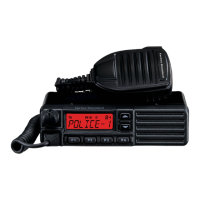
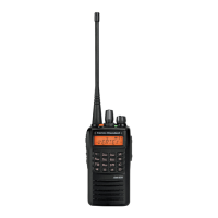
VX-920/-920E VHF series Service Manual
Alignment
Introduction
The VX-920/-920E series is carefully aligned at the
factory for the specified performance across the fre-
quency range specified for each version. Realign-
ment should therefore not be necessary except in
the event of a component failure, or altering ver-
sion type. All component replacement and service
should be performed only by an authorized Vertex
Standard representative, or the warranty policy may
be void.
The following procedures cover the sometimes crit-
ical and tedious adjustments that are not normally
required once the transceiver has left the factory.
However, if damage occurs and some parts subse-
quently are placed, realignment may be required. If
a sudden problem occurs during normal operation,
it is likely due to component failure; realignment
should not be done until after the faulty component
has been replaced.
We recommend that servicing be performed only
by authorized Vertex Standard service technicians
who are experienced with the circuitry and fully
equipped for repair and alignment. Therefore, if a
fault is suspected, contact the dealer from whom the
transceiver was purchased for instructions regard-
ing repair. Authorized Vertex Standard service tech-
nicians realign all circuits and make complete per-
formance checks to ensure compliance with factory
specifications after replacing any faulty components.
Those who do undertake any of the following align-
ments are cautioned to proceed at their own risk.
Problems caused by unauthorized attempts at re-
alignment are not covered by the warranty policy.
Also, Vertex Standard reserves the right to change
circuits and alignment procedures in the interest of
improved performance, without notifying owners.
Under no circumstances should any alignment be
attempted unless the normal function and opera-
tion of the transceiver are clearly understood, the
cause of the malfunction has been clearly pinpoint-
ed and any faulty components replaced, and realign-
ment determined to be absolutely necessary.
The following test equipment (and thorough famil-
iarity with its correct use) is necessary for complete
realignment. Correction of problems caused by mis-
alignment resulting from use of improper test equip-
ment is not covered under the warranty policy.
While most steps do not require all of the equip-
ment listed, the interactions of some adjustments
may require that more complex adjustments be per-
formed afterwards. Do not attempt to perform only
a single step unless it is clearly isolated electrically
from all other steps. Have all test equipment ready
before beginning, and follow all of the steps in a sec-
tion in the order presented.
Required Test Equipment
RF Signal Generator with calibrated output level
at 200 MHz
Deviation Meter (linear detector)
In-line Wattmeter with 5 % accuracy at 200 MHz
50 Ohm RF Dummy Load with power rating 10
W at 200 MHz
16 Ohm AF Dummy Load (Attention : Audio out-
put is BTL output)
Regulated DC Power Supply (standard 7.5 V DC,
3 A)
Frequency Counter with 0.2 ppm accuracy at 200
MHz
Audio Generator
AC Voltmeter
DC Voltmeter
VHF Sampling Coupler
IBM PC / compatible Computer with Microsoft®
Windows® 95 or later operating system
Vertex Standard CE59 (version 2.06 or later)
Alignment program and CT-109 PC Program-
ming Cable or FIF-10A
USB Interface/CT-108 PC
Programming Cable
: When using the FIF-10A USB Interface, requires
the Windows® 2000 or Windows® XP
 Loading...