14
VX-920/-920E VHF series Service Manual
Alignment
CH (C
HANNEL
-
BY
-C
HANNEL
) Fine Alignment Mode
The CH Fine Alignment Mode allows you to align
the radio separately for every operating channel. The
value of each parameter can be changed to the de-
sired position using the “
” / “
” and up/down
arrow keys, direct number input, and by dragging
the PC mouse.
To enter the CH Fine Alignment Mode, select “CH
Fine Alignment” in the main “Radio” menu. It will
start to “Upload” the written personalized data from
the radio. Pressing the “OK” button will then start
the CH Fine Alignment Mode.
Note: Detailed information for each step may be
found in the “Help” file within CE59 (Clone Editor).
Note!
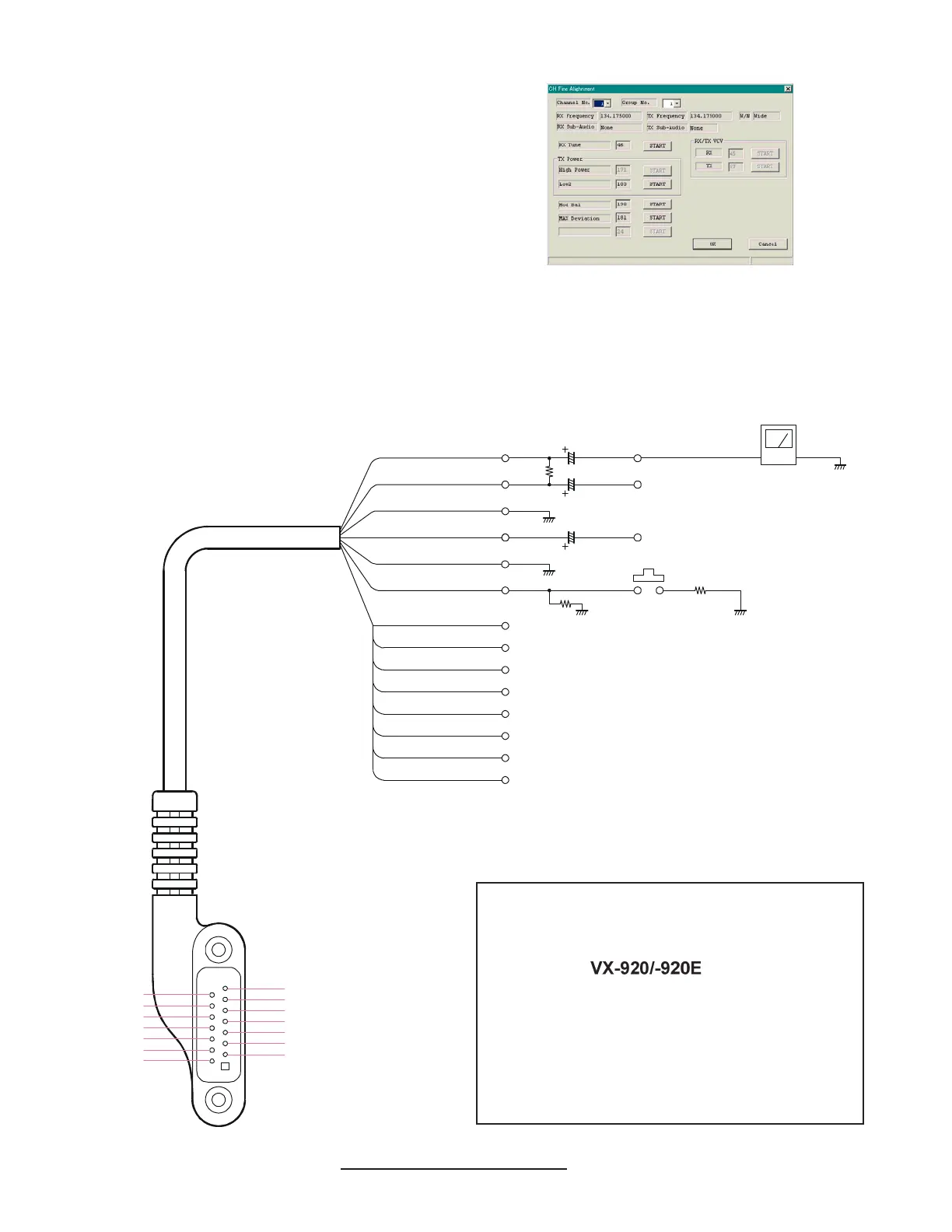
Because of the bridge audio amplifier circuit
used in the
, it is necessary to
construct and use a simple audio load test
adapter as shown in the schematic diagram,
when conducting receiver alignment steps.
Do not connect either side of the speaker leads
to chassis “ground.”
AF TEST ADAPTER SCHEMATIC
Pin 1: SP
(
+
)
Pin 3: GND
Pin 5: SELECT
Pin 7: CLONE
Pin 9: DISC OUT
Pin 11: VCCP
Pin 13: TXD
Pin 4: BLACK
Pin 5: BLUE
Pin 6: YELLOW
Pin 7: GRAY
Pin 8: GREEN
Pin 9: PURPLE
Pin 10: ORANGE
Pin 12: CLEAR
Pin 13: PINK
Pin 14: BROWN
Pin 11: L
_
GREEN
Pin 3: SHIELD
Pin 2: RED
Pin 1: WHITE
16-Ohm 2W
27 k-Ohm
2.2 k-Ohm
220 µF
220 µF
10 µF
AUDIO GENERATOR
PTT SW
1/2 OUTPUT LEVEL
AF METER
Pin 2: SP
(- )
Pin 4: MIC
Pin 6: PTT/ACC
Pin 8: 5V
Pin 10: SEL
Pin 12: RESET
Pin 14: RXD
-
VXSTD P/N: T9207094