Note: Do not connect to the stainless steel bolt heads to make this measurement.
Dual Interconnections
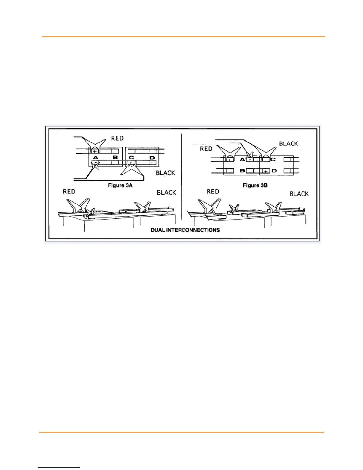
Figures (3A) and (3B) below, show the typical intercell connections for dual post cells. This type of
interconnection requires that two readings be taken.
The first one shown should be with the intercell leads connected from Terminal Post A to Terminal Post
C. Take the second reading with the intercell leads connected from Terminal Post B to Terminal Post D.
The positive (a red clip) Cellcorder lead should remain connected (as shown) to the same terminal post
for both measurements.
Figure 97 - (Figure 3A and 3B) Connections for Dual Posts.
Triple Interconnections
Figures (4) and (5) show the typical intercell connections for triple post cells. For cells arranged as in (Fig.
4), three readings are made. The first one, shown, should be with the intercell leads connected from
Terminal Post A to Terminal Post D. Take the second reading with the intercell leads connected from
Terminal Post B to Post E. The third reading is with the intercell leads connected from Terminal Post C to
Post F.

 Loading...