User Manual 10H52258UM60 - Rev. 3 - 01/2019
42
APM 400/600 Operation Control and Display
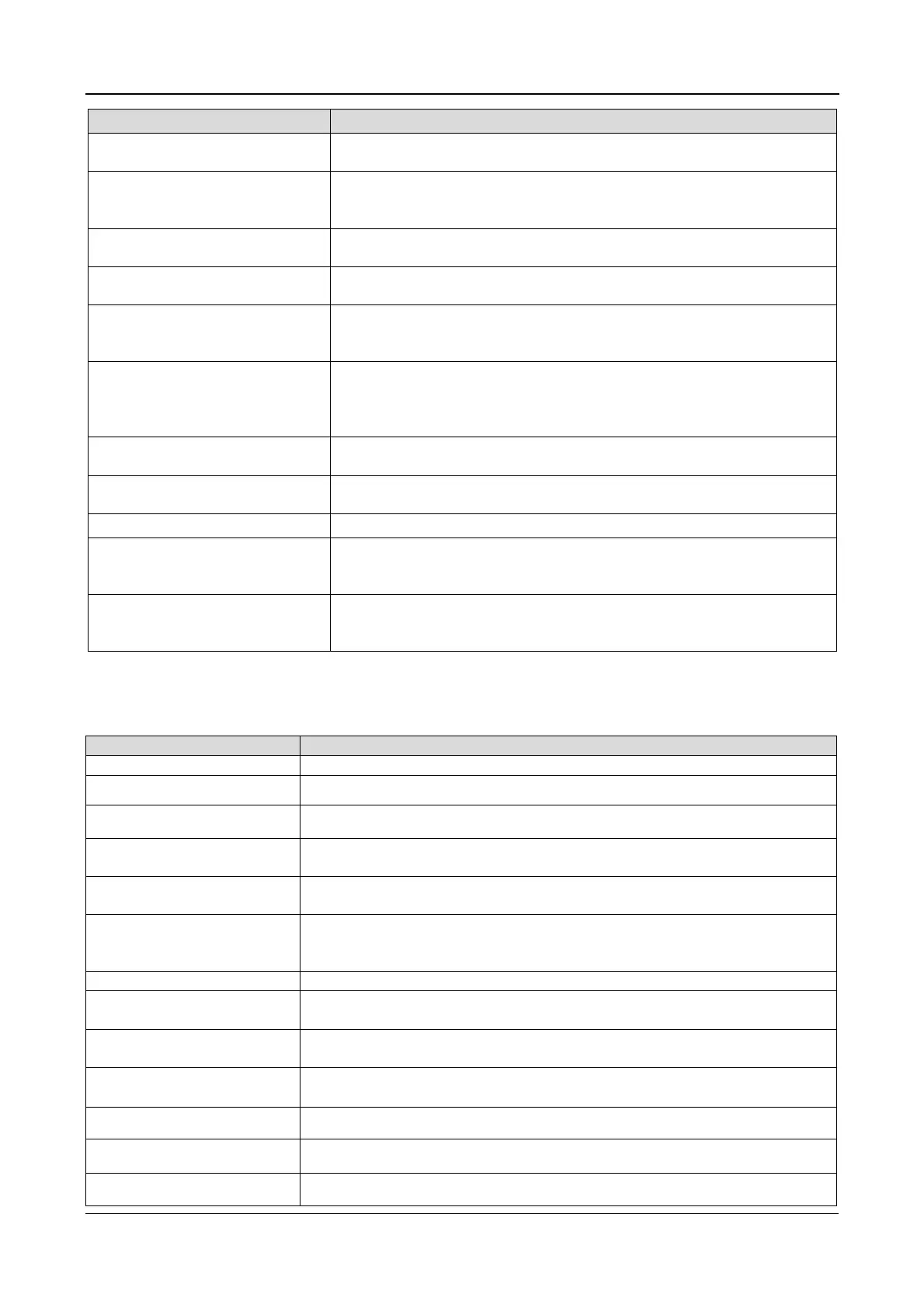
Prompt Description
confirm or cancel
The load executes an interval transfer between the inverter and bypass
The load is too high to be
transferred without interruption
The total load must be less than the capacity of one UPS
a parallel system to perform an uninterrupted transfer from bypass to
inverter
UPS output, confirm or cancel
off the inverter will cause the load to
be de-energized
This operation leads to inverter
overload, confirm or cancel
off this inverter will lead to the overload of the remaining
inverter(s) in a parallel system
Switch on more UPS to supply
current load
The number of inverters already switched on is insufficient to supply the
current load. The user is requested to switch additional UPS units on
Battery will be discharged,
confirm or cancel
, the battery will discharge until the
UPS shuts down. This requests the user to confirm the test. If the user
opts to cancel rather than confirm, the test is abandoned and the UPS
reverts to inverter mode
everything is OK
No action required
warnings
Check the active alarm messages
Enter control password Required for battery or UPS test (default: 12345)
Battery Self Test aborted,
conditions not met
Battery self-test condition is not met. Please check if the battery is in
boost charge state and the load is greater than 20% of the nominal value
Battery Top-up Charge aborted,
conditions not met
when battery top-up charge conditions are not met (e.g. no battery,
charger failure)
5.8.5
Alarm List
Table 5.9 below describes all the alarm messages that are displayed either on the Event menu or Record menu.
Table 5.9
FAULT CLEAR key on the operator co
ntrol and display panel pressed
Rectifier in Setting The rectifier starts up and is in synchronization
Inverter in Setting The inverter starts up and is in synchronization
Inverter Manual On
INVERTER ON key on the operator control and display panel
in order to switch the inverter on
Inverter Manual Off
key on the operator control and display panel
pressed in order to switch the inverter off
Turn On Fail
switch on when the INVERTER ON key wa
may be the result of an invalid operation (maintenance bypass switch closed)
or DC bus or rectifier not ready
This alarm is generated if the DC bus voltage is low
Silence Active
acoustic alarm has been enabled by p
the operator control and display panel
Silence Inactive
The acoustic alarm has been deactivated by pressing the
key on the operator control and display panel
Bypass Mode The UPS is in bypass mode
Normal Mode The UPS is in normal mode
Battery Mode The UPS is in battery mode
Check UPS Output UPS shutdown with no output power





 To Next Page