User Manual 10H52258UM60 - Rev. 3 - 01/2019
44
APM 400/600 Operation Control and Display
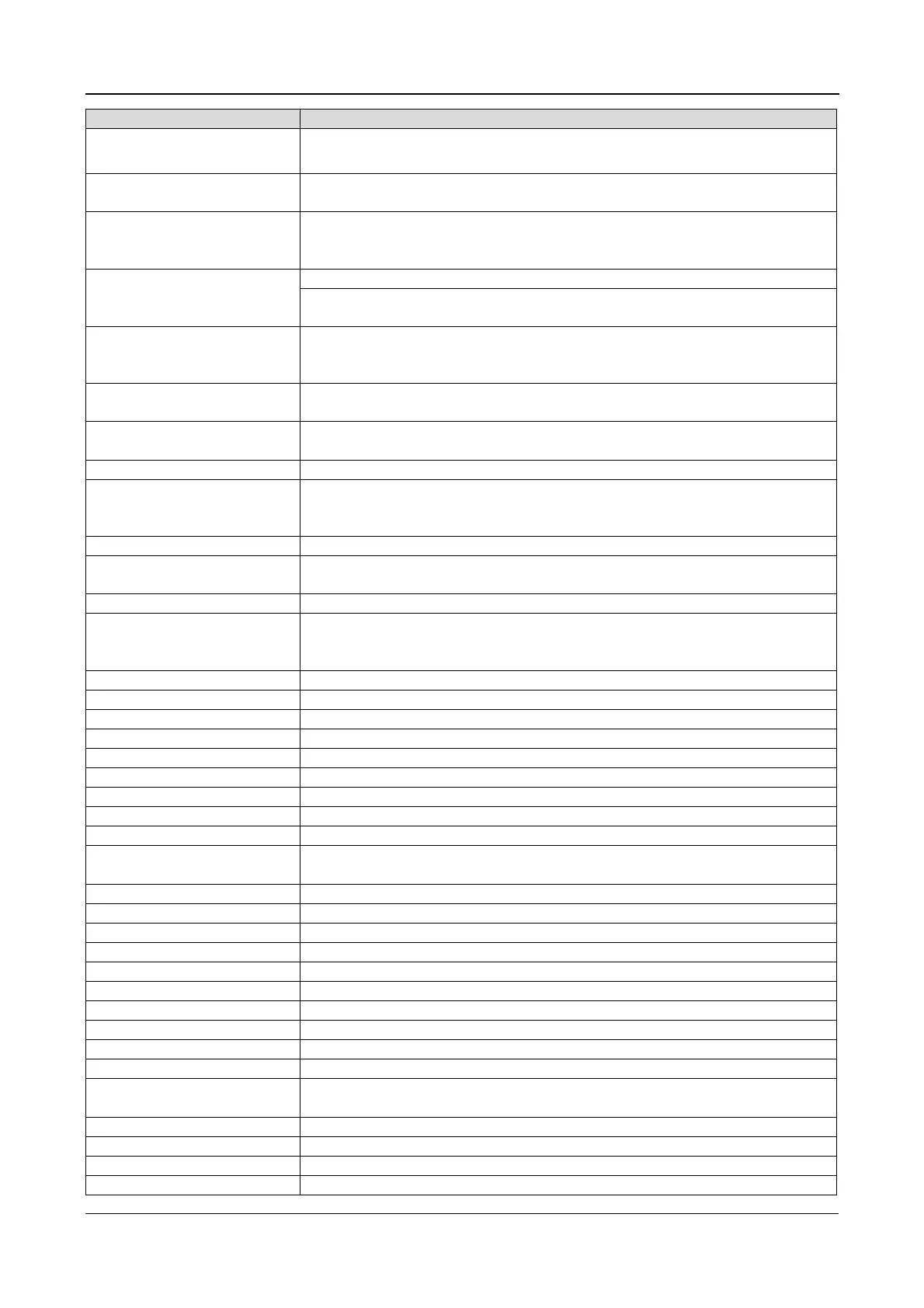
Output Volt. Abnormal At least one phase of the output voltages is abnormal
Output Overload
This alarm appears when the load
alarm is reset automatically once the overload condition is resolved
System Overload
alarm appears when the total load
105% of the nominal rating of
the parallel system. This alarm is reset automatically once the overload
condition is resolved
Out. Overload Timeout
and the overload times out.
has expired, the load automatically transfers to the
bypass
Load Impact Transfer
A transfer to bypass occurred due to a large step load. The UPS can recover
automatically. Switch the load equipment on in stages in order to reduce the
impact on the inverter
Excess Auto Rexfers
The load remains on bypass power
due to the excessive number of transfers
that have occurred during the past hour
Excess ECO Auto Xfers
The load remains on bypass power
due to the excessive number of transfers
that have occurred during the past hour
in a parallel system are not sharing the load current correctly
Other Module Xfer
in the parallel system transfer to bypass at the same time when
one of them needs to transfer to bypass. This message appears on the UPS
LCD as passive transfer to bypass
uxiliary power failure or power
EPO
operator control and display panel
a remote EPO command has been received
Operation Invalid
aintenance bypass switch is closed when the parallel system is on
inverter, or the output and maintenance bypass switches are closed when the
inverter is running
aintenance bypass switch is open
aintenance bypass switch is closed
There is a fault on the battery charger
ischarge current is over limit, close the discharger
Auto start
After UPS shutdown at EOD, the inverter automatically start
power is restores
Rectifier DSP software being updated
Rectifier FPGA software being updated
Inverter FPGA software being updated
Bypass DSP software being updated
Bypass FPGA software being updated
Monitoring software being updated
Historical record not saved
Remote Turn On Fail
Caused by invalid operation (maintenance bypass switch closed), DC bus or
rectifier not ready
Check the battery and battery connection





 To Next Page