45
User Manual 10H52258UM60 - Rev. 3 - 01/2019
Operation Control and Display APM 400/600
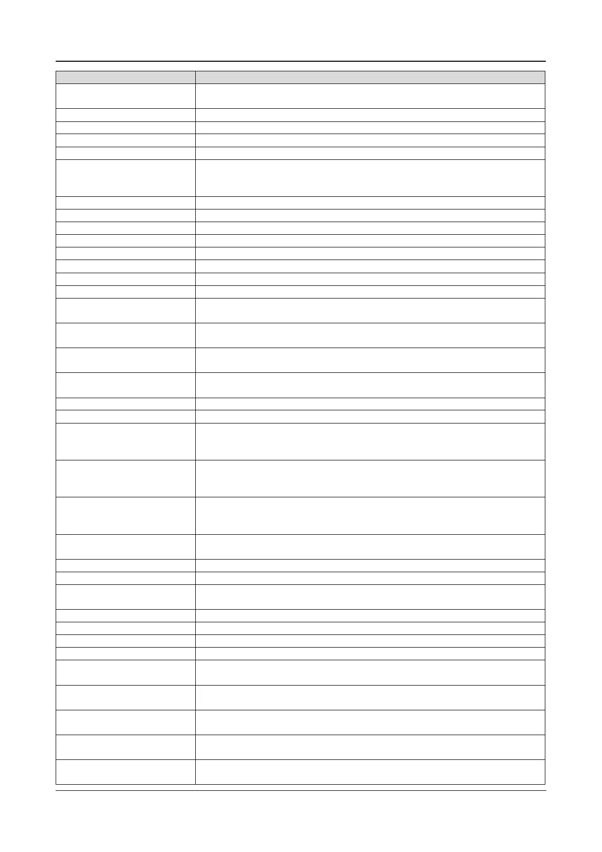
Battery Period Testing
odic battery maintenance test
(20% capacity discharge)
initiated a battery capacity test (100% capacity discharge)
initiated a maintenance test (20% capacity discharge)
The battery temperature is over limit
Low Battery Warning
Before the EOD, battery low pre
warning will occur. After this pre
remaining battery capacity will be sufficient for another 3 minutes at with full
load. This interval may be set-up by the user to between 3 and 6 minutes
Dry contact signal, indicating generator connected
over temperature (option included)
Logic conflict between BCB1 drive
signal and feedback signal
At least one mains fuse has blown, and the rectifier is disconnected
Bypass Fuse Failure
At least one bypass fuse has blown, and the system transition to bypass is
disabled
Output Fuse Failure
At least one output fuse has blown, the inverte
r is disconnected, and the
system is in Bypass mode
Equalize Chg. Timeout
The actual float charging time exceeds the time set
software
MonCAN Comm. Abnor.
internal monitoring board and inverter,
rectifier and bypass
inverter, rectifier and bypass
ParaPowerCANCommAbnor.
Communication failure between different UPSs in parallel system. Check i
of the UPS units are de-energized or if any of the parallel cables are not
connected correctly, then clear the fault in order to restart the UPS
Discr.BusComm.Abnor.
the discrete bus inside the rack.
confirming that the rear communication cables inside the rack are connected
reliably
ParaDiscrBusCommAbnor.
the discrete bus inside the rack.
confirming that the rear communication cables inside the rack are connected
reliably, and that the bypass module is secured properly
Ambient Overtemp.
limit threshold; this value may be set
the configuration software
The internal bypass module
System Interrupt Xfer
Execute the interval transfer under conditions of bypass un
inverter phase not locked
Loss of redundant capacity
Pwr. Hardware Mismatch
The model information set
the host is inconsistent with the act
situation
Module Overtemp.
temperature condition on the rectifier and inverter power components
inside the module
Charger Overtemp.
temperature condition on the charger power components inside the
module
Equalize Chg. Timeout
float charging time exceeds the time
configuration software
MonCAN Comm. Abnor.
internal monitoring board and inverter,
rectifier and bypass





 To Next Page