81
User Manual 10H52258UM60 - Rev. 3 - 01/2019
Optional Components APM 400/600
Closed if no alarm conditions are present
Closed if summary alarm occurs
Closed if On UPS (inverter) power
1. Insert the relay card into the UPS.
Note
1. The relay card should be installed in Intellislot port 1 or 3 (we recommend Intellislot port 3).
which means that it may be installed
without shutting down the UPS.
a) Remove the Intellislot port (see Figure 3-3) cover on the bypass module, keep the screws and cover in a safe
place for future use.
b) Align the relay card with the Intellislot port, insert the relay card by sliding it along the grooves on either side
of the port.
c) Secure the relay card in place via the fixing holes on the relay card panel using the screws left over from step 1.
Connect the cable.
Warning
1. The terminal block connectors must be connected to a SELV circuit. Failure to observe this could damage the
relay card and even lead to accidents.
2. The external equipment must meet the electrical parameter requirements set out in Table 8-2, failure to observe
this could cause damage to the dry contact output terminal.
For more detailed information about this utility, refer to the Liebert
®
Intellislot IS-Relay card user manual in the
accessories section.
9.1.6
LBS Adapter
The LBS adapter is designed to extend the LBS function up to 150m between the 2 UPS modules or systems of a
dual bus system. It also enables an APM UPS to synchronize with other UPS models.
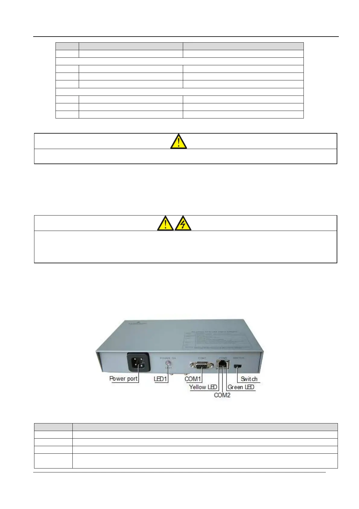
The appearance of the LBS adapter is illustrated in Figure 9-5.
Figure 9-5 Illustration of a real-time LBS adapter
Table 9.3 lists the ports, LED indicators, and switches present on the LBS adapter:
Table 9.3
phase A, neutral and ground
LBS signal port. Connect to
COM2
RS485 port. Connect to the other LBS adapter.
Green LED. On = The communication power is OK; Off = Communication power failure.