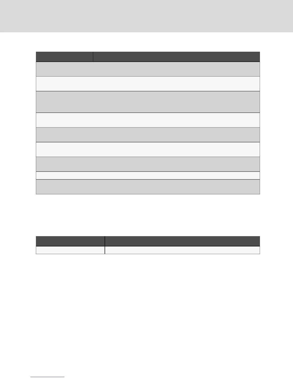
Digit Description
Digit 15 = Coil Option
1 = Non-coated coil
Digit 16 = Enclosure Option
6 = Liebert® standard pebble-gray color
Digit 17 = High-voltage option
L = Locking disconnect
6 = Locking disconnect + ATS
Digit 18 = Option packages
0 = None
Digit 19 = Monitoring Cards
U = 1 Liebert® IS-UNITY-DP card
Digit 20 = Sensors
0 = None
Digit 21 = Packaging
P = Domestic
Digit 22 to 24 = Factory Configuration Number
Digit 25 = Configuration Code
S = SFA
Table 2.2 DSE500 Packaged Solution Model-number Digit Definitions (continued)
2.2 Component Location
The unit component locations are described in the submittal documents included in the Submittal
Drawings on page53.
The following table lists the relevant documents by number and title.
Document Number Title
DPN004717 Component Location, Perimeter Unit
Table 2.3 Component-location Drawings
Vertiv | Liebert® DSE500™ Installer/User Guide
10