3.2 Connections and System Setup
3.2.1 Electrical Connections
• Three-phase electrical service is required for all models. Electrical service must conform to
national and local electrical codes. See equipment nameplate for details.
• Plan the routing of wiring and ductwork to the unit. Refer to the appropriate electrical-
connection drawings for your system in Submittal Drawings on page53.
NOTE: Verify that all electrical connections, service-access doors unit and ducting connections to the
building are sealed and water-tight. Failure to do so risks damage to the outdoor unit.
Document Number Title
DPN004710 Electrical Connections Enclosure
Table 3.2 Electrical Field-connection Drawings
3.2.2 Evaporator Drip-pan Connection
Connect the evaporator clean-out line to an adequate water-drain system. See Figure 3.1 below, for the
connection on the unit. Observe the following requirements and 3.2 above, when installing and routing
the clean-out line:
• Insulate the line with a heat trace so it will not freeze.
• The line must be the full size of the drain connection. The connection port is 1-in. pipe with
CPVC 1-in. FPT fitting.
• Slope the drain line continuously away from the unit, and pitch the drain line toward the drain.
• The line must be made of a material that is suitable for draining water and be rigid enough that
it does not sag between supports, which creates unintentional traps.
• The drain line must comply with all applicable codes.
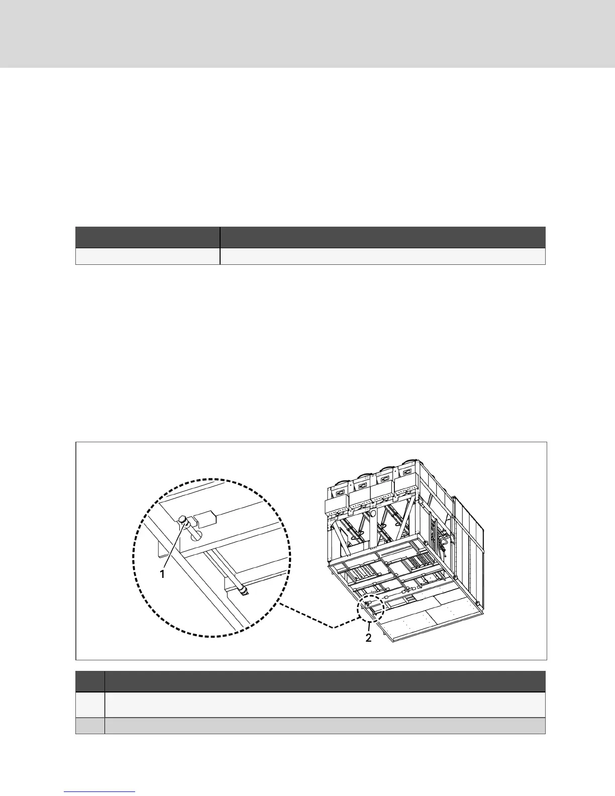
Figure 3.1 Drip-pan clean-out line location
Item Description
1
Water drain connection for evaporator drip pan. Accessed by remove the floor panel above it (next to the compressor
compartment).
2 Location of the drip-pan clean-out line in the perimeter unit.
Vertiv | Liebert® DSE500™ Installer/User Guide
14