Vertiv™ NetSure™ 5100 Series -48 VDC Power System User Manual
Proprietary and Confidential © 2022 Vertiv Group Corp.
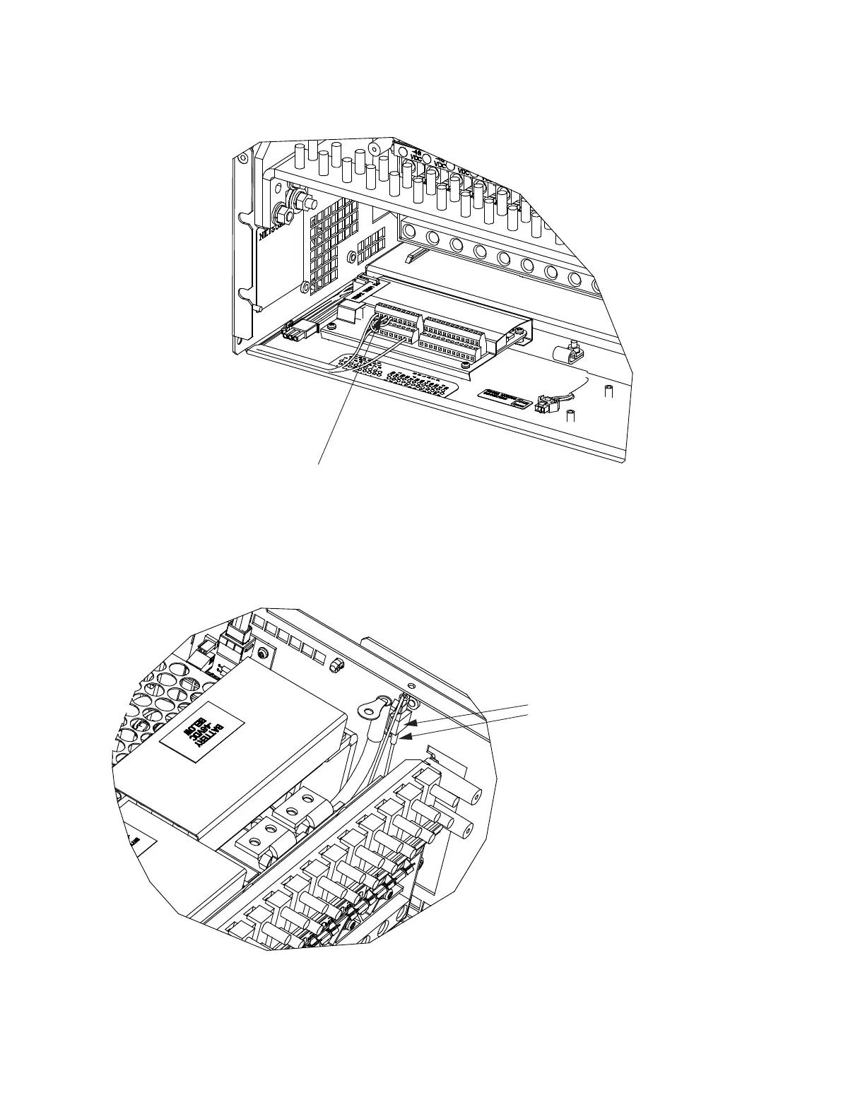
Figure 4.24 Connecting Violet Wire to IB2 DI2+
10. Locate the faston connector secured to the inside side wall of the distribution cabinet (see Figure 4.25). Disconnect the wire
with the tab from the faston connector. Insulate and tie back
Figure 4.25 Disconnecting Alarm Jumper
11. Remove the voltage/polarity label plug buttons for positions 23 through 26 of the distribution panel as shown in Figure 4.26.
12. Remove the voltage/polarity label for positions 23 through 26 of the distribution panel, then turn over the label to show other
polarity.
Locate violet wire in this area.
Connect to “Digital Input 2+” (DI2+) on the IB2.
Disconnect the Alarm Jumper by
Separating the Tab from the
Faston Connector Here

 Loading...


