Use standard Cat5 communications cables.
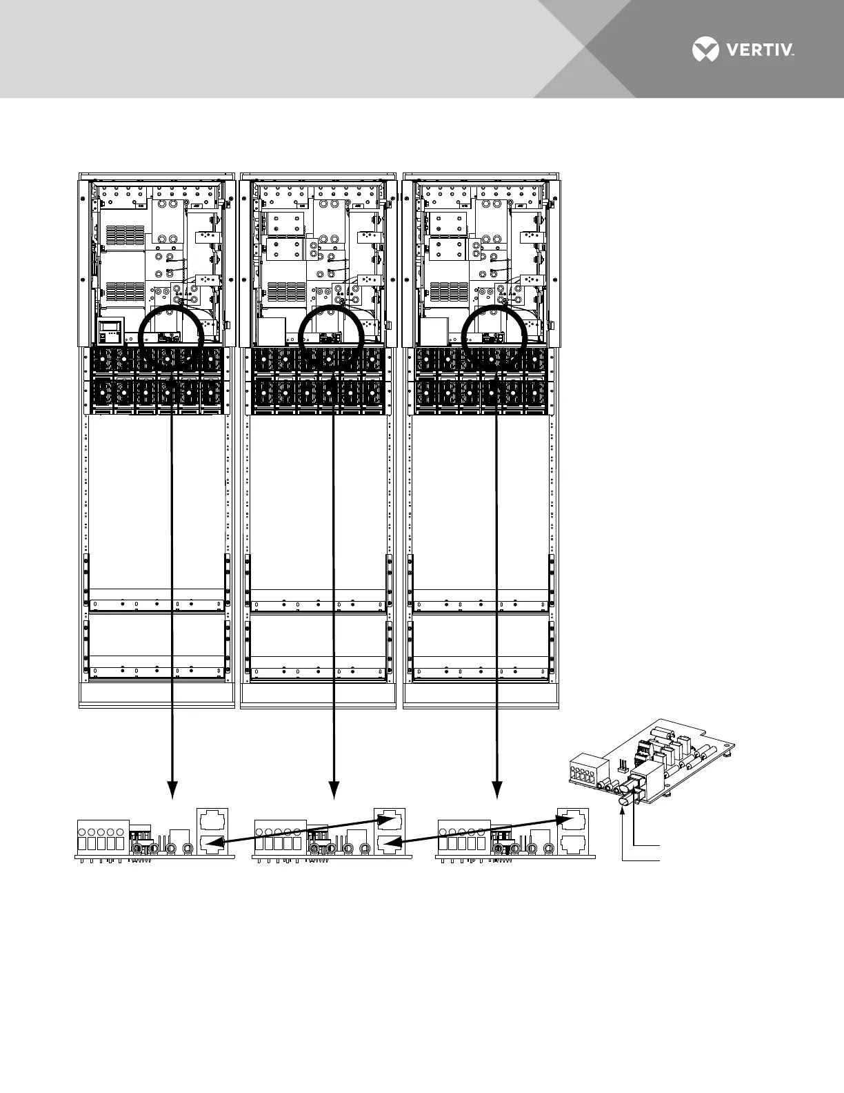
1. Remove terminating plug from bottom connector on the System Interface Circuit Card installed in the Main Bay
and place in bottom connector on the System Interface Circuit Card in the last bay.
2. Connect the bottom connector on the System Interface Circuit Card installed in the Main Bay
to the top connector on the System Interface Circuit Card installed in the 1st Supplemental Bay.
3. Connect the bottom connector on the System Interface Circuit Card installed in the 1st Supplemental Bay
to the top connector on the System Interface Circuit Card installed in the 2nd Supplemental Bay.
Main Bay 1st
Supplemental
Bay
2nd
Supplemental
Bay
System Interface
Card in Main Bay
System Interface Card
in 1st Supplemental Bay
System Interface Card
in 2nd Supplemental Bay
Front doors remove in
illustration for clarity only.
CAN termination plug
must be installed (if
port is not used).
System Interface
Card in Last Bay
CAN2
CAN1
IN
OUT
IN
OUT
 Loading...


