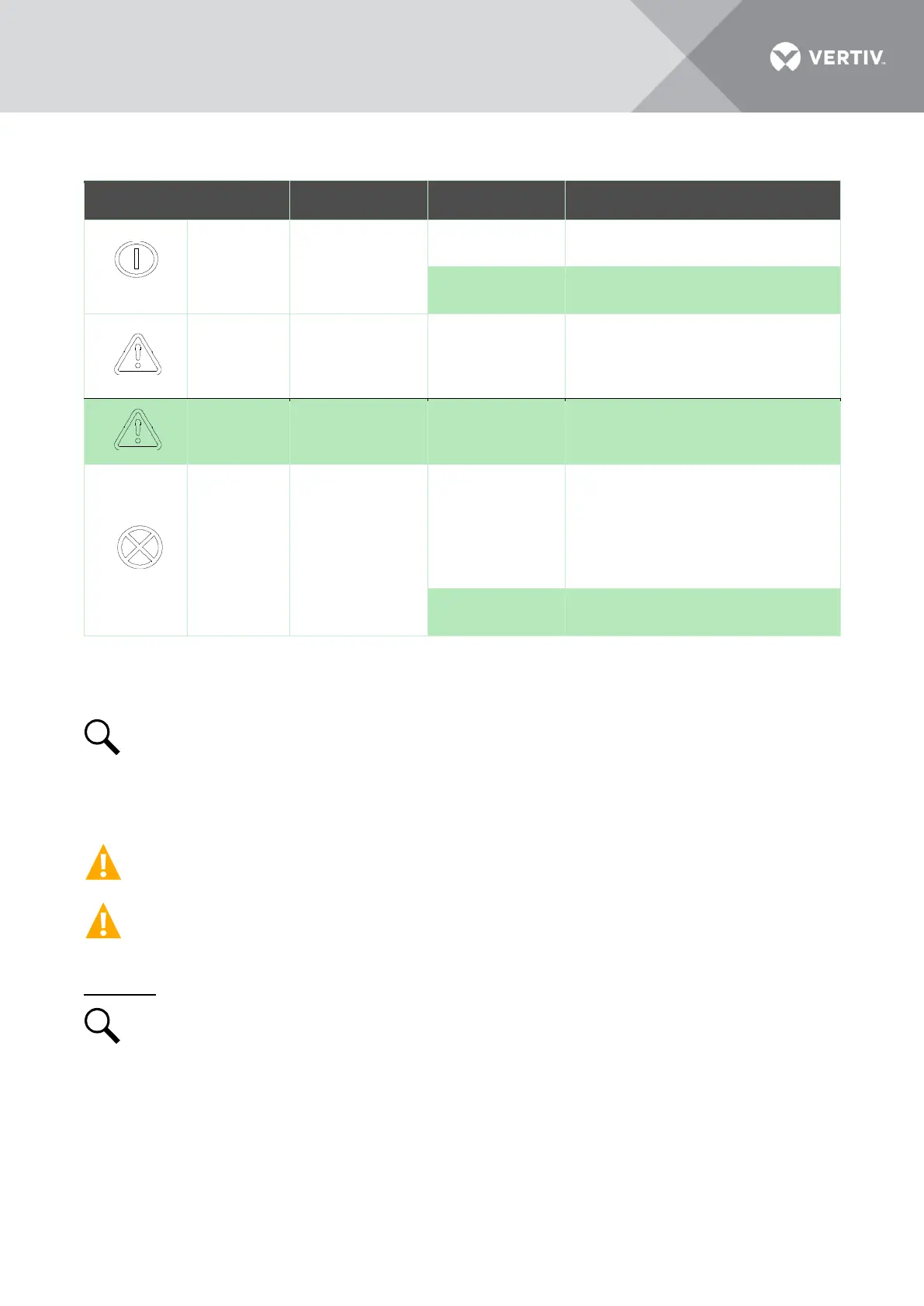
AC input under/over voltage.
PFC output under/over voltage.
High temperature.
Moderate load sharing imbalance.
Severe load sharing imbalance.
rectifier module output disabled
for any reason, including
overvoltage shutdown and internal
output fuse open.
Rectifier addresses contradictory.
Installing Rectifiers
Rectifier modules can be inserted or removed with power applied (hot swappable).
NOTE! Each rectifier module locks into a module mounting shelf by means of a latch located
on the bottom of the module. The latch and rectifier module handle are interactive. Pushing
the handle up into the module’s front panel causes the latch to extend to the locking position;
pulling the handle down out from the module’s front panel causes the latch to retract. See
Figure 6.
CAUTION! Single fuse in L line for protection. All-pole circuit breaker should be provided
when used in IT power system, or if N line cannot be distinguished during field installation.
WARNING! To prevent damage to the latching mechanism, ensure the handle is in the open
position when installing or removing a rectifier module. NEVER hold the handle in the closed
position when installing a rectifier module into a shelf.
Procedure
NOTE! Refer to Figure 6 as this procedure is performed.
1. Unpack the module.
2. Place the module into an unoccupied mounting slot without sliding it in completely.
3. Loosen the captive screw on the module’s handle. Pull the handle down out from the module’s
front panel (this will also retract the latch mechanism). See Figure 6.
4. Push the module completely into the shelf.
 Loading...


