EasyManua.ls Logo

Vertiv VRC100 - Installing the VRC Unit into the Rack

Vertiv VRC100
70 pages
Print Icon
To Next Page IconTo Next Page
To Previous Page IconTo Previous Page
Loading...
17
Vertiv I VRC Self-Contained System I User Manual
Figure3-2 Overall layout of the system
3.2.2 Overall layout of the VRC unit
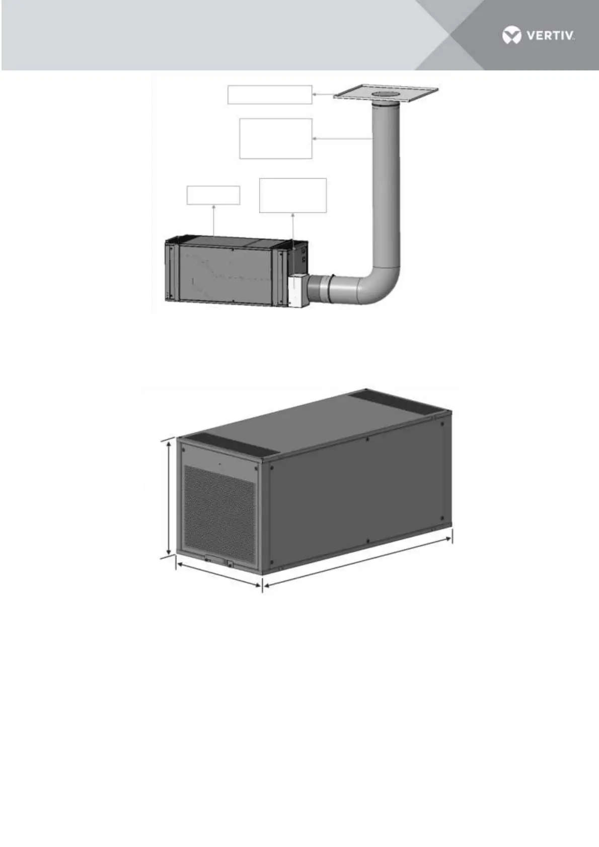
The overall layout of the unit is depicted in the Figure 3-2 below.
Figure 3-3 Overall layout of the unit
3.3 Installing the VRC Unit into the Rack
The installation process for the cooling unit consists of mounting the unit inside the cabinet, connecting
the condenser duct and the drain piping.
3.3.1 Evaporator filter installation
The filter is installed on the air return side of the evaporation side.
Ceiling Tile Unit
Flex Duct
Max length=3.8
m/12.5 ft
VRC1 Unit
Condensate
Pump Unit
439 mm
(17.3 in)
442 mm
(17.4 in)
978 mm
(38.5 in)

Table of Contents

Other manuals for Vertiv VRC100

Related product manuals