3.4.6 Dimensional recommendations
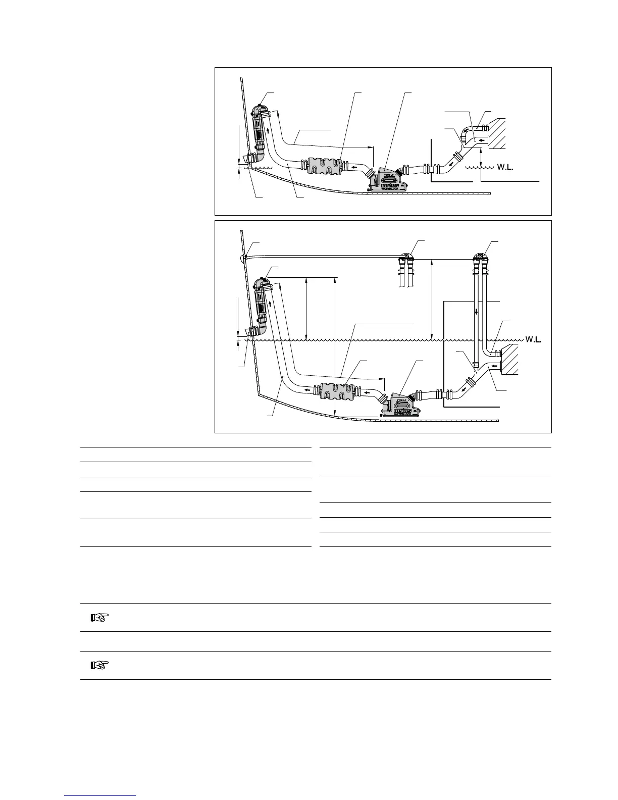
System with water injection point
15 cm (6 in.) or more above the
waterline
System with water injection point
below or less than 15 cm (6 in.)
above the waterline
1 Exhaust manifold
2 Cooling water
3 Water injection point
4 Waterlock,
WLOCKL40R / WLOCKL50R / WLOCKLP60
5 Muer,
DEMPMP40 / DEMPMP50 / DEMPMP60
6 Goose neck,
WLOCKLT40 / WLOCKLT50 / WLOCKL60
7 Transom tting,
TRC40R / TRC50R / TRC60R
8 Exhaust hose
9 Air vent
10 Through hull tting
3.4.7 Waterlock capacity
NOTE
The waterlock is sized to hold multiples of the volume of water that spills back from the
exhaust highest point when the engine shuts o.
IMPORTANT
Prolonged cranking of the starter may cause excessive sea water to build up between
the engine and the high point.
Each time cranking is interrupted additional water may spill back into the muer. In time this cumulative spill back can
ood the engine. Unusual cranking and/or cranking interruptions must be monitored and the muer drained before
excessive water build-up occurs. This may be made more convenient by installing a suitable, non-corrosive valve at the
muer drain tting.
MIN. 15 cm (6”)
1
3
2
L=MAX. 300 cm
(10 ft)