20
Automatic current cutback release signal
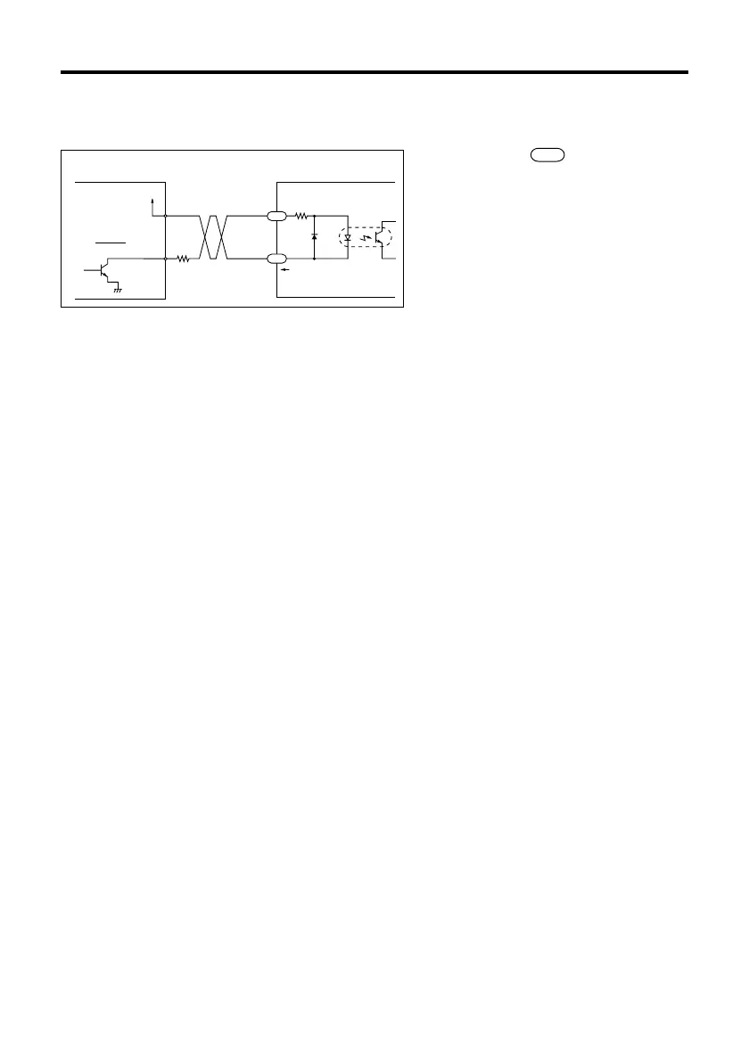
The diagram below shows the input circuit and an example connection to a controller.
The number within refers to the pin
number of driver connector SIGNAL 2.
Keep the voltage between DC5V and DC24V.
When voltage is equal to DC5V, external
resistance R is not necessary.
When voltage is above DC5V, connect
external resistance R, and keep the input
current below 20mA.
R
+
220Ω
20mA max.
Controller output
Open collector
output
‑
Driver input
(Internal circuit)
C.UP
C.UP
1
2
V
0
• When the automatic current cutback release signal is in the “photocoupler OFF” state,
the automatic current cutback function is activated; 0.1s. after the pulse is stopped the
motor output current is automatically cut back, reducing motor and driver heat.
(The factory setting for the current cutback is 50%. In order to change this, refer to the
instructions for adjusting the current at motor standstill on pages 25, 26)
• When the maximum holding torque is needed, input “photocoupler ON” signal. The
automatic current cutback function is deactivated.
• When the automatic current cutback release signal is in the “photocoupler ON” state,
the automatic current cutback function is deactivated.
• Because the motor’s holding power is proportional to the motor output current, the motor’s
holding power is reduced when the current is cut back. (The motor has holding power
proportional to the current at motor standstill, which is set with the STOP potentiometer.
Refer to page 24.)
Note
Generally, automatic current cutback release signal should be set to “photocoupler OFF”
to suppress heat generation in the motor and driver.