21
The excitation timing signal is output to indicate when the motor excitation (current flowing
through the winding) is in the initial stage (step “0” at power up ).
The excitation timing signal can be used to increase the accuracy of home position
detection by setting mechanical home position of your equipment (photo-sensor etc.) to
coincide with the excitation sequence initial stage (step “0”).
When connected as shown in the example connection, the signal will be “photocoupler
ON” at step “0”.
The excitation timing signal is output simultaneously with a pulse input each time the
excitation sequence returns to step “0”.
The excitation sequence will complete one cycle for every 7.2° rotation of the motor output
shaft.
When the power is turned ON, the excitation sequence is reset to step “0”.
Relation to the step angle switch
When the switch is set to the F position:
Full step: signal is output once every 10 pulses
(Standard type: 0.72°/step, Geared type: 0.72°× / step)
When the switch is set to the H position:
Half step: signal is output once every 20 pulses
(Standard type: 0.36°/step, Geared type: 0.36°× / step)
Timing chart when in full step mode
Output signals
The output signals from the driver and their functions are specified below.
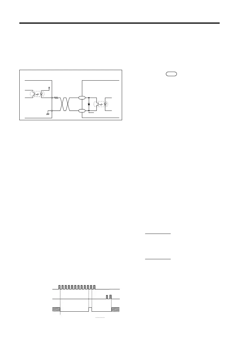
Excitation timing signal
The diagram below shows the output circuit and an example connection to a controller.
The number within refers to the pin
number of driver connector SIGNAL 2.
Keep the voltage between DC5V and DC24V.
Keep the current below 10mA.
If the current exceeds 10mA, connect external
resistance R.
1
gear ratio
1
gear ratio
Controller output
Driver input
(Internal circuit)
V
0
R
10mA max.
TIM
3
4
+
‑
Pulse
Rotation direction
Excitation timing
output
123456789101112
12
Step
1
123456789012
0
0
 Loading...