Select the Volts dc, Volts ac, Resistance
or Frequency function and range on the
meter and the input level from the 5520A.
The display should meet the request listed
in Section 6.
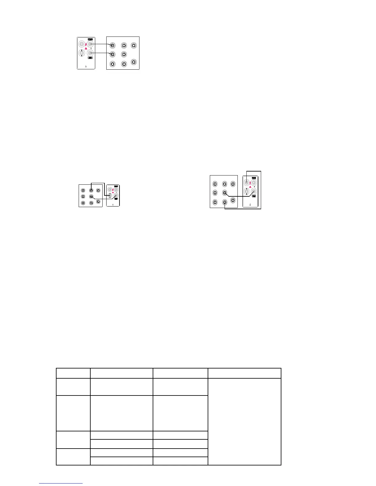
2. Connect a test lead from the output AUX
HI and LO connectors of the 5520A to the
mA and COM connectors on the meter
(see Figure 4-2). Select the Current ac or
Current dc function and 300mA range on the meter and the input level from the 5520A. The
display should meet the request listed in Section 6.
3. Connect a test lead from the output 20A HI and LO connectors of the 5520A to the 10A and
COM connectors on the meter (see Figure 4-3). Select the Current dc or Current ac function and
10A range on the meter and the input level from the 5520A. The display read should meet the
request listed in Section 6.
SERVICE
If you suspect that the meter has failed, review this manual to make sure you are operating it
correctly. If the meter still fails to operate properly, pack it securely (in its original container if
available) and forward it, postage paid, to the nearest Service Center. Assumes no responsibility for
damage in transit.
SECTION 5
Calibration
INTRODUCTION
To ensure the accuracy and the stability of the meter, the meter should be calibrated on a regular cycle of one
year.
REQUIRED EQUIPMENT (refer to the table5-1)
Table5-1. Recommended Test Equipment
Measurement Multifunction Range Accuracy±
(%Output)
Recommended Equipment
DCV 300mV,3V,30V,300V,
1000V
0.0002
FLUKE
5520A
ACV 300mV,3V,30V,300V,
1000V
20~50Hz 0.025
50 Hz~10KHz 0.015
10~20KHz 0.022
20~50KHz 0.03
OHMS 300Ω,3KΩ,30KΩ, 300KΩ 0.004
3MΩ,30 MΩ,100 MΩ 0.05
DCA 0.3mA, 3mA, 30mA, 300mA 0.025
10A 0.1
 Loading...