I-751.Europe / European Alarm Check Valve Stations / Installation, Maintenance, and Testing Manual
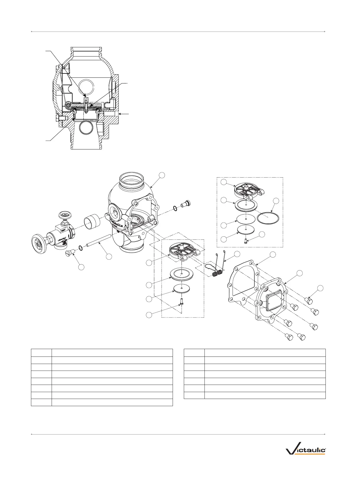
INTERNAL VALVE COMPONENTS – SECTION VIEW AND EXPLODED VIEW DRAWINGS
Clapper Seal
Clapper
Seat
Exaggerated for Clarity
Valve is shown in the “set” position
Alarm Outlet
All Other Valve Sizes
8-inch/DN200 Valve Size Only
3
4
4
6
13
7
5
9
8
6
7
8
1
2
12
10
11
Item Description Item Description
1 Valve Body 8 Self-Sealing Screw
2 Clapper Shaft Retaining Bushings 9 Cover Plate Gasket
3 Clapper Shaft 10 Cover Plate
4 Clapper 11 Cover Plate Bolts
5 Clapper Spring 12 Clapper Seal Ring
6 Clapper Seal 13 Clapper Seal Washer
7 Clapper Seal Retaining Ring
I-751.Europe_8REV_G

 Loading...


