I-751.Europe / European Alarm Check Valve Stations / Installation, Maintenance, and Testing Manual
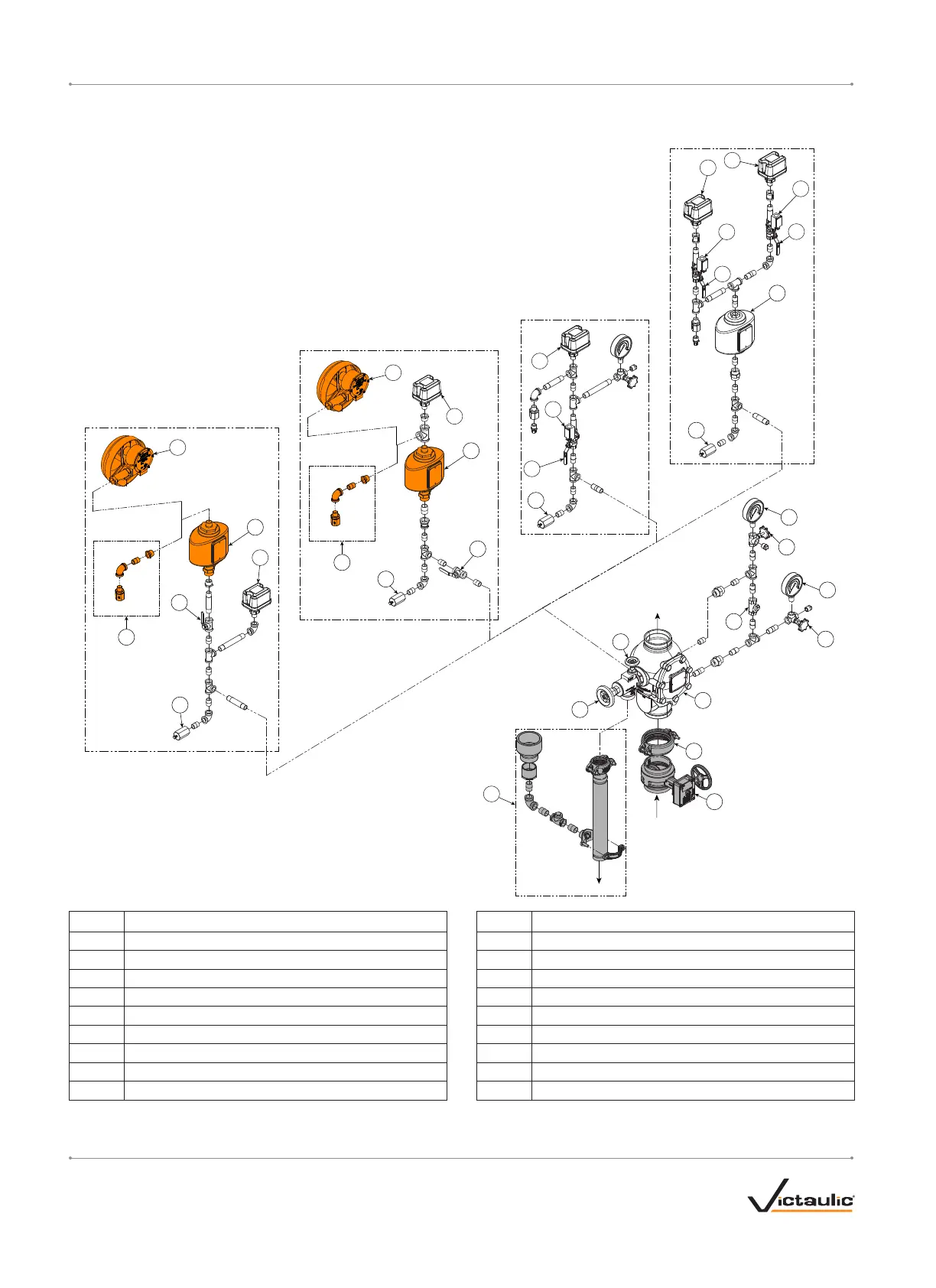
TRIM COMPONENTS – EXPLODED VIEW DRAWING
11
13
7
8
10
5
4
6
9
1
12
15
16
4
To Drain
To Drain
To Drain
To Drain
To System
10
10
10
2
3
To Drain
From
Water
Supply
Gray shaded areas identify components that are standard when the VQR is ordered.
Orange shaded areas identify components that are optional equipment.
All non-shaded components are standard for their respective trim congurations.
Normally Open
(Lockable)
To Drain
To Drain
11
11
12
12
12
13
Normally
Open
(Lockable)
14
12
14a
14a
14
14
14a
17
Optional Series 752V
Retard Vent Kit
To Optional Water Motor
Alarm or Series 752V
Retard Vent Kit
Optional Series 752V
Retard Vent Kit
To Optional Water Motor
Alarm or Series 752V
Retard Vent Kit
Pipe to Open Drain
Pipe to Open Drain
15
16
VdS, CE, UKCA, FM, EAC
SBSC
FG
LPCB
Item Description Item Description
1 Series 751 FireLock™ European Alarm Check Valve 10 Restricted Orifice/Alarm Line Drain
2 FireLock™ Rigid Coupling
1
11 Series 752 VdS Retarding Chamber
3 Water Supply Main Control Valve
1
12 Alarm Pressure Switch
4 Gauge Valve 13 Alarm Line Ball Valve
5 Water Supply Pressure Gauge 14 Alarm Line Monitoring Limit Switch Assembly
6 Swing Check Valve 14a Alarm Line Monitoring Ball Valve
7 System Pressure Gauge 15 Series 760 Water Motor Alarm
8 System Test Valve 16 Series 752V Retarding Vent Kit
2
9 System Main Drain Valve 17 Drain Connection Kit
1
Items 2 and 3 are provided standard when the SBSC and FG trim are ordered. For the SBSC and FG trim, an additional coupling and water supply main control valve
are available as an option for installation above the Series 751 FireLock European Alarm Check Valve (system side).
2
The Series 752V Retarding Vent Kit is required any time an air break is needed above the Series 752 VdS Retarding Chamber. In addition, the Series 752V Retarding
Vent Kit is required if multiple valves are tied into one water motor alarm and a check valve isolates each line.
I-751.Europe_7 REV_G

 Loading...


