I-751.Europe / European Alarm Check Valve Stations / Installation, Maintenance, and Testing Manual
RESETTING THE SYSTEM
Step 1:
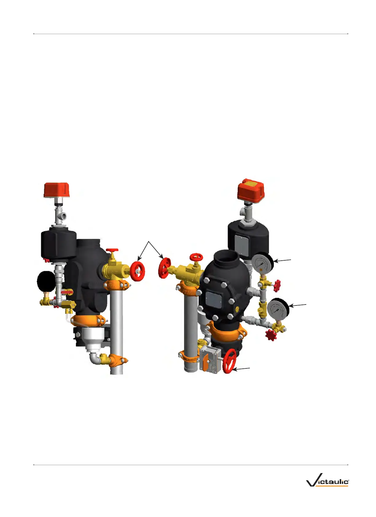
Close the water supply main control valve (Item 3).
Step 2:
Open the system main drain valve (Item 9). Confirm that the system is
drained.
Step 3:
Close the system main drain valve (Item 9).
Step 4:
Confirm that all system drains are shut and that the system is free
from leaks.
Step 5:
Confirm that the system has been depressurized. The gauges (Items 5
and 7) should indicate zero pressure.
Step 6:
Follow steps 5 – 11 of Section I, Initial System Setup.
Water Supply Main
Control Valve
(Item 3, Step 1)
System Main
Drain Valve
(Item 9,
Steps 2 & 3)
System
Pressure Gauge
(Item 7, Step 5)
Water Supply
Pressure Gauge
(Item 5, Step 5)
VDS, CE, UKCA, FM, EAC VERSION SHOWN
I-751.Europe_12REV_G

 Loading...


