4
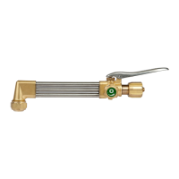
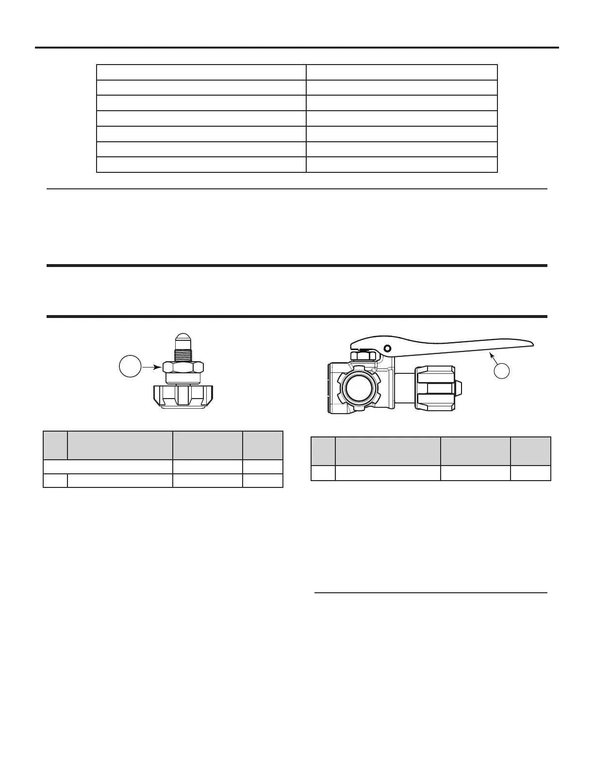
3.03 CONTROL VALVE REPAIR KIT
1
Control Valve
Item
No.
Description Part number Qnty
Control Valve Repair Kit 0390-0086 1
1 Valve Stem Assembly 0662-0102* 1
*Sold as part of kit only
Service
• Wipe with dry cloth. Do not use any cleaning solvents.
• Check for leaks.
Disassembly
1. Place torch in a vise.
2. Use a wrench to unscrew the Control Valve Nut.
Assembly
1. Apply Christo-Lube to threads.
2. Screw Control Valve Assembly into Cutting Torch Body.
3. Use a wrench to tighten the Control Valve Nut.
4. Apply green colored “O” (Oxygen) decal on knob.
5. Remove from vise.
SECTION 3: SERVICE & REPAIR INSTRUCTIONS
3.01 RECOMMENDED TOOLS & SUPPLIES FOR REPAIR PROCEDURES
5/8”, 9/16”, 11/16”, and 1/2” Open-End Wrenches Vise
1” Box-End Wrench 45% Silver Solder
5/32” Drift Punch Silver Solder Flux
Small Hammer Loctite
®
#222 (Part Number 0028-0081)
Cone End Assembly Clamp RT-108 Christo-Lube 129 (Part Number 0034-0021)
Brazing Torch Hand Reamer RT-58
Pliers Air Hose
NOTE
Disconnect cutting torch from any gas lines or other hardware before beginning any service or repair.
3.02 CLEANING PROCEDURES
Contact your local chemical supplier for recommended cleaning solvents applicable to the metals used in this product. Always use
cleaning solvents in accordance with the manufacturer’s instructions.
WARNING
DO NOT allow nonmetal components (Seat, O-Rings, Dust Seal, Gaskets) to contact cleaning solvents! Cleaning solvents cause elastomeric
and plastic parts to swell and stress crack. If these parts require cleaning, use a mild soap solution, followed by a thorough rinsing in water.
Dry these parts completely before installing. REPLACE NONMETAL PARTS THAT HAVE COME IN CONTACT WITH OIL, GREASE OR ANY OTHER
PETROLEUM-BASED SUBSTANCE! Petroleum-based substances become dangerously flammable in the presence of oxygen.
3.04 CUTTING LEVER
1
Cutting Lever
Item
No.
Description Part number Qnty
1 Cutting Lever 0307-0035 1
Service
• Check Roll Pin for wear.
• Check Lever Tabs for alignment to Oxy Valve Groove.
Disassembly
1. Using Punch, tap Roll Pin out of Lever Handle and Cutting
Torch Body. Inspect and discard Roll Pin if deformed.
NOTE
Replacement Roll Pin part number is 1404-0047.
2. Slide Lever Handle forward.
Assembly
If Roll Pin was discarded, acquire a replacement Roll Pin before
beginning this step.
1. Align Lever Tabs with Valve Stem.
2. Conrm Lever Tabs align with Valve Stem Groove and insert
Roll Pin into Lever and Torch Body.
3. Gently tap in Roll Pin.
 Loading...