6
Assembly
1. Clean Gas Feed Tube ends of all solder and debris.
2. Place new 400 Series Head on Gas Feed Tubes. Conrm
correct orientation to 400 Series body.
3. Ensure that the center tube is pressed rmly against the
mixer of the head.
4. Solder ttings and allow to cool before beginning the next
step.
5. Use RT-58 to nish hand reaming torch seat.
6. Remove all chips and debris around seat area.
7. Reattach the Control Valve Assembly (See Section 3.03,
Control Valve Repair Kit) and H.P. Oxy Valve (See Section
3.05, H.P. Oxy Valve Repair Kit).
8. Reattach the Cutting Lever (See Section 3.04, Cutting
Lever),Tip Nut, and Tip.
9. Check for leaks.
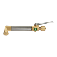
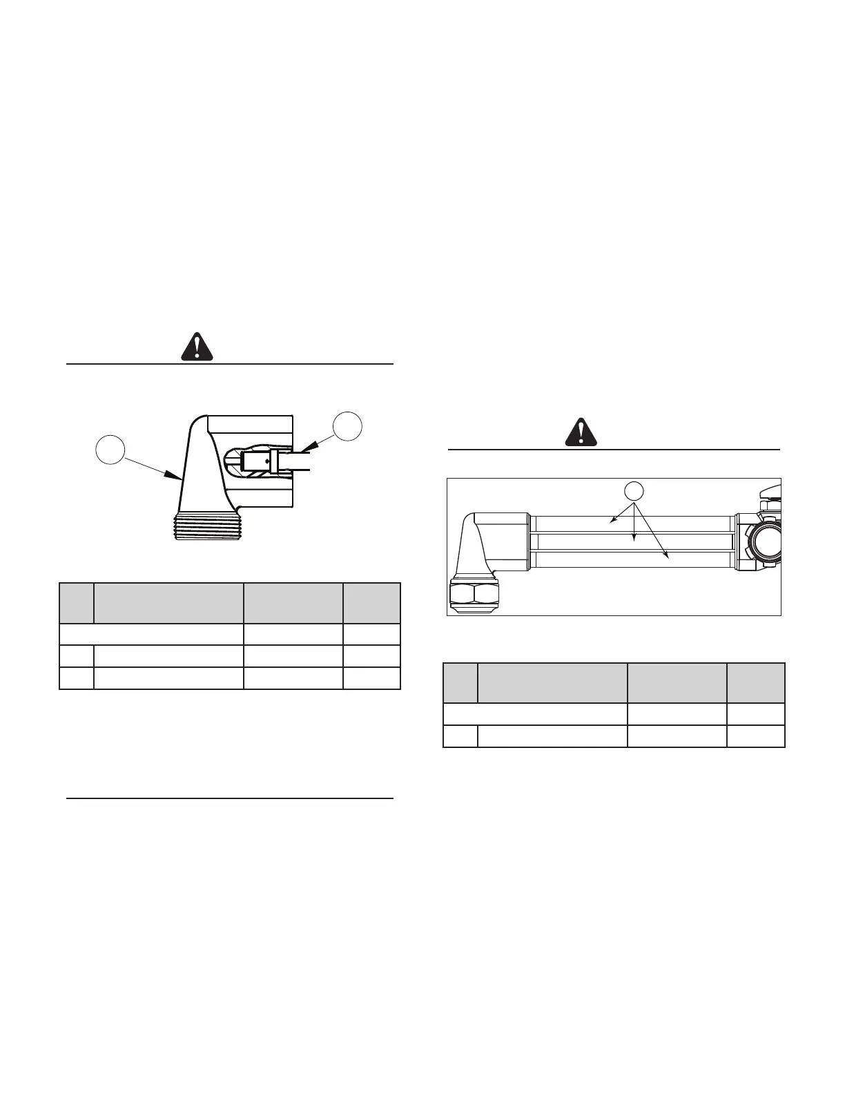
3.08 GAS FEED TUBES
CAUTION
Always wear gloves when handling heated parts.
1
Gas Feed Tubes
Item
No.
Description Part number Qnty
Gas Feed Tubes 0390-0091 1
1 5/16” Tube 0303-0190* 3
*Sold as part of kit only.
Service
• Check tubes for leaks and wear.
Disassembly
Remove the Tip, Tip Nut, Cutting Lever, Control Valve Assembly,
H.P. Oxy Valve, Cone End, and 400 Series Head before beginning
this task.
1. Place the torch body in a vise, positioned so that you have
full access to the Gas Feed Tubes.
2. Heat the Gas Feed Tubes until solder liquees. Use pliers to
remove all tubes.
3. Allow the torch body to cool before beginning assembly.
Assembly
1. At the beginning of the Cone Assembly thread, apply a
small amount of Loctite
®
. Loctite
®
must completely cover
the beginning two threads of the Cone Assembly end.
2. Screw Cone End Assembly into Cutting Torch Body.
3. Place torch in RT-108 by mounting Cone End in xture.
4. Immediately use a wrench to tighten the Cone End Assembly
into the Cutting Torch Body. Consider using a small hammer
to tap wrench tighter to seat threads and set Loctite
®
.
5. Remove from RT-108.
6. Reattach Cutting Lever. (See Section 3.04, Cutting Lever)
7. Check for leaks.
3.07 400 SERIES HEAD REPAIR KIT
CAUTION
Always wear gloves when handling heated parts.
1
2
400 Series Head
Item
No.
Description Part number Qnty
90° Victor Series 3 Head Repair Kit 0390-0089 1
1 400 Series-3 Head-90° Victor 0302-0257* 1
2 Mixer 0305-0334* 1
*Sold as part of kit only.
Service
• Remove Tip Nut and Tip and use an air hose to clear any
debris from opening. Reattach Tip Nut and Tip.
NOTE
Repair kit does not include Tip Nut. Tip Nut part number is
0309-0003.
Disassembly
Remove the Tip, Tip Nut, Cutting Lever, Control Valve Assembly,
and H.P. Oxy Valve before beginning this task.
1. Place the torch body in a vise, positioned so that you have
full access to the 400 Series Head.
2. Heat the Gas Feed Tubes until solder liquees. Use pliers
to remove 400 Series Head.
 Loading...