7
Assembly
1. Clean the torch body of all solder and debris.
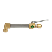
2. Place a new 400 Series Head in a vise, positioned so that the tube bores face up.
3. Insert the Gas Feed Tubes into the 400 Series Head, followed by the torch body. Conrm correct orientation to the 400 Series
Head.
4. Ensure that the center tube is pressed rmly against the mixer of the head.
5. Solder the ttings around the 400 Series Head and repeat for the torch body side. Allow to cool before beginning the next step.
6. Complete steps 5 - 9 in Section 3.07, 400 Series Head Repair Kit, Assembly.
SECTION 4: TEST PROCEDURES
4.01 RECOMMENDED TOOLS & SUPPLIES FOR TEST PROCEDURES
Oil-free air or dry nitrogen supplies 2-3-101 Cutting tip
Oxygen and acetylene gas supplies
5/8”, 9/16”, 11/16”, and 1/2” Open-End Wrenches
Small water tank
1” Box-End Wrench
4.02 LEAK TEST THE GAS REGULATOR
1. Close the Cylinder Valves.
2. Turn the Pressure Adjusting Screws one turn counterclockwise. If the High Pressure Gauge reading drops, there is a leak in the
Cylinder Valve, Inlet Fitting, or High Pressure Gauge. If the Low Pressure Gauge drops, there is a leak in the Torch Handle Valve,
Hose, Hose Fitting, Outlet Fitting, or Low Pressure Gauge. If the High Pressure Gauge drops, and at the same time the Low
Pressure Gauge rises, there is a leak in the Regulator Seat. Have a qualied repair technician repair the Regulator.
3. Use an approved leak detector solution to check for leaks.
4.03 LEAK TESTING THE TORCH
1. Connect the Torch to oil-free air or dry nitrogen supply lines with matching type regulator.
2. Insert a plugged cutting tip into Torch.
3. Pressurize the hoses to 50+/-5 PSIG.
4. Completely submerse the Torch in water.
5. Open the Valve Stem Assemblies. Check for leaks around all external connections. Observe the Valve Stem Assemblies. If bubbles
are escaping from around the Valve Stem Assembly packing, tighten the Packing Nut until it takes 1-1/4 to 2 in-Ibs of torque to
adjust the Valve Stem Assembly knobs.
6. Close the Valve Stem Assembly knobs to a torque of 7-8 in-Ibs.
7. Remove the Plugged Cutting Tip from the torch. Observe the Torch Head. If bubbles appear at the Torch Head, one or both of the
Valve Stem Assemblies is leaking. Ream the Valve Seating surface using RT-33 reseating tool. Repeat steps 2 through 7.
4.04 FLAME TESTING THE TORCH
1. Remove the Torch from the water. Open the Valve Stem Assemblies for 10 seconds. Once all the water has been removed from
the Torch, disconnect the hoses from the oil-free air or dry nitrogen supply. Attach them to oxygen and acetylene gas supplies.
2. Install a 2-3-101 cutting tip in the head. Tighten the Tip Nut to 10-15 ft-Ibs of torque.
3. Adjust the oxygen to deliver 40+/-5 PSIG. Adjust the acetylene to deliver 8+/-3 PSIG.
4. Open the Oxygen Valve and purge the oxygen line for ve seconds. Then, close the Oxygen Valve. Open the Fuel Valve and purge
the fuel line for ve seconds.

 Loading...