DIGITAL MULTIMETER INSTRUCTION MANUAL
1. SUMMARY
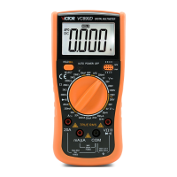
This 3 3/4 digital multimeter with highly stable performance is driven by 2 pieces 1.5V battery. It
uses a LCD with 32mm high figure, which makes the reading clearer and the operation more
convenient.
The digital multimeter holds functions of measuring DCV, ACV, DCA, ACA, resistance, capacitance,
frequency, temperature, duty cycle, transistor, diode, and continuity, etc. It also can provide special
functions including unit symbol display, data holding, relative value measuring, auto/manual range
switching (RANGE), auto power off and warning alarm. To assure high accuracy and resolution, it
adopts an 4-bit microprocessor and a dual integral A/D conversion IC as its core which can drive
LCD directly. It is an ideal tool for labs, factories and radio-technology.
2. SAFETY PRECAUTIONS
The instrument is designed according to IEC1010 standard (safety standard issued by International
Electro technical Committee). Please read the following before operation.
2.1 Check the connection and insulation of test leads to avoid electric shock.
2.2 To avoid electric shock and damage to the meter, do not input voltage higher than DC 1000V or
AC 750V during measurement.
2.3 When measuring voltage higher than DC 60V or AC 40V, please be careful.
2.4 Select correct function and range to avoid fault operation.
2.5 Please move the test leads away from test points when switching the function.
2.6 Please don’t input voltage in current terminal.
2.7 Please don’t modify the circuit arbitrarily, it may cause safety problem.
2.8 Introduction for safety symbols:
“
” exists high voltage, “ ” GND, “ ” dual insulation, “ ” Operator must refer to manual,
“
” Low battery indication.
3. FEATURES
3.1 General Characteristics
3.1.1 Display: LCD;
3.1.2 Max display: 4000 (3 3/4) digits, automatic polarity and unit symbol display;
3.1.3 Measurement method: double integral A/D conversion;
3.1.4 Sampling rate: approx.3 times/sec.
3.1.5 Over-range display: “OL” displayed in the highest digit.
3.1.6 Low battery display: “
”
3.1.7 Working environment: (0~40)℃, relative humidity: <80%;
3.1.8 Store condition: (-10~50)℃, relative humidity: <80%
3.1.9 Power supply: 2pcs 1.5V battery (“AAA”7# battery);
3.1.10 Dimension: 185×93×35mm (length*width*height);
3.1.11 Weight: approx. 290g (including battery);
3.1.12 Accessories: test leads, user manual, TP01 temperature probe, gift box, and 2*1.5V batteries.
3.2 Technical Features
3.2.1 Accuracy: ± (a% × reading data + digits). To assure accuracy, the environment temperature
should be (23±5) ℃, relative humidity should <75%. One year guarantee since production date.
3.2.2 DC Voltage(DCV)
Range Accuracy Resolution
400mV
±(0.5%+4)
0.1mV
4V 1 mV
40V 10 mV
400V 100 mV
1000V ±(1.0%+4) 1V
Input impedance: at 400mv range >40MΩ, at other ranges is 10MΩ.
Overload protection: 1000V DC or 750V AC peak value
3.2.3 AC Voltage(ACV)
Range Accuracy Resolution
400mV ±(1.5%+6) 0.1mV
4V
±(0.8%+6)
1 mV
40V 10 mV
400V 100 mV
750V ±(1.0%+6) 1V
Input impedance: at 400mv range >40MΩ, at other ranges is 10MΩ.
Overload protection: 1000V DC or 750V AC peak value
Frequency response: at 750V range: 40~100Hz, at other ranges: 40~400Hz
Displaying: sine wave RMS (average value response)
3.2.4 DC Current(DCA)
Range Accuracy Resolution
400uA
±(1.0%+5)
0.1μA
4000uA 1μA
40mA 10μA
400mA 100μA
4A 1mA
20A ±(2.0%+5) 10mA
Maximum voltage drop: 400mV for mA range, and 200mV for A range
Maximum input current: 20A (for 15 seconds).
Over load protection: 0.5A/250V fast action fuse and 13A/250V fast action fuse.
3.2.5 AC Current(ACA)
Range Accuracy Resolution
400uA
±(1.5%+5)
0.1μA
4000uA 1μA
40mA 10μA
400mA 100μA
4A 1mA
20A ±(2.0%+10) 10mA
Maximum voltage drop: 400mV for mA range, and 200mV for A range
Maximum input current: 20A (for 15 seconds).
Over load protection: 0.5A/250V fast action fuse and 13A/250V fast action fuse.
Frequency response: 40~100Hz under 10A range, 40~400Hz at other ranges.
3.2.6 Resistance(Ω)
Range Accuracy Resolution
400Ω ±(0.8%+5) 0.1Ω
4kΩ ±(0.8%+1) 1Ω
40kΩ 10Ω
400kΩ 100Ω
4MΩ 1kΩ
40MΩ ±(1.2%+5) 10kΩ
Open circuit voltage: 400mV.
Overload protection: 250V DC/AC peak value
NOTE: At 400Ω range, short the test leads first to measure the wire resistance and then
subtracts it from the real measurement. Or press “REL” to clear the wire resistance and read the
value directly.
3.2.7 Capacitance(C)
Range Accuracy Resolution
4nF ±(2.5%+6) 1pF
40nF
±(3.5%+8)
10pF
400nF 100pF
4μF 1nF
40μF 10nF
200μF ±(5.0%+8) 100nF
Overload protection: 250V DC/AC peak value
WARNING: Do not input any voltage at this range! The capacitor must be completely
discharged before making measurement. When measuring in line capacitor, make sure the
power is cut off before testing.
3.2.8 Frequency(F)
Range Accuracy Resolution
10Hz
±(0.5%+4)
0.001Hz
100Hz 0.01Hz
1000Hz 0.1Hz
10kHz 1Hz
100kHz 10Hz
1MHz 100Hz
30MHz 1kHz
Input sensitivity: 0.7V.
Overload protection: 250V DC/AC peak value.
3.2.9 Transistor (hFE)
Measurement Range Test conditions
hFE NPN or PNP 0~1000
Base current is approx 15uA,
Vce is about 4.5V
3.2.10 Diode and Continuity Test
Range Description Test Conditions
Diode forward voltage drop
Forward DC current is
approx 0.5mA, reverse
voltage is approx 1.5V.
When the resistance under test is
less than 70±10Ω, buzzer sounds
Open circuit voltage:
0.5V