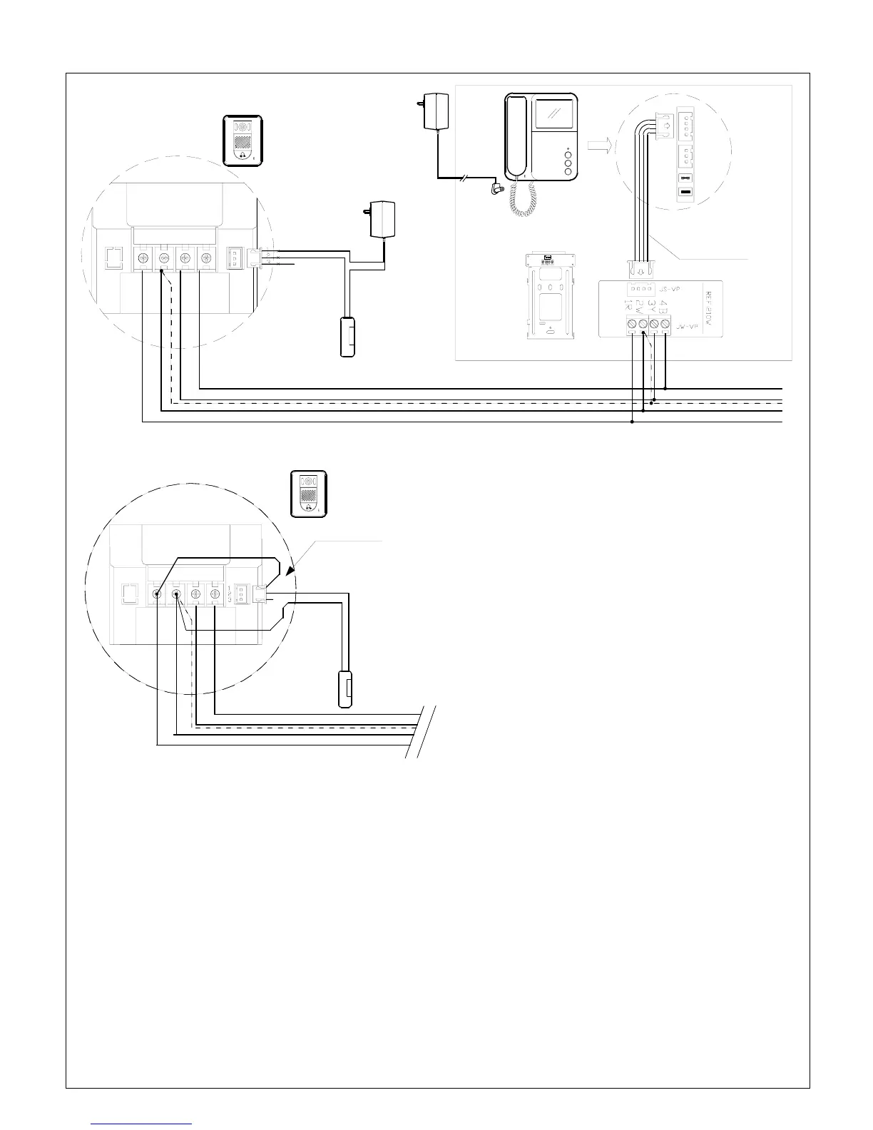
System connection with one camera and a monitor IMPORTANT!! Please read page 9 & 10 for cable
requirements BEFORE running cables.
OUTDOOR STATION
VS-902C/MC
VS-952C/MC
* NOTE5
* NOTE1
* NOTE 4
Ref.VS-4P
DC IN
16VDC Power supply
Ref. VS-902PSU
MONITOR
VS-902(P)M
VS-952(P)M
JS-VP
JS-AP
JP-LK : Reserved
JP-VD
BACK
MOUNT BRACKET
4B3Y2W1R LB
POWER SUPPLY
FOR DOOR LATCH
* NOTE 5
Parellel connection to
next Monitor(s)
Fig. 11 Dry contact mode
Fail-Secure
Door Latch
(Ref SL-ST-160)
*Broken line indicates Shield wire if any
OUTDOOR STATION
VS-902C/MC
VS-952C/MC
4B3Y2W1R LB
Fig. 12 : DC output mode
Fail-Secure
Door Latch
(Ref SL-ST-160)
* Note 2
Red wire
*Broken line indicates Shield wire if any
NOTE 1: JP-LK is used for Unlock operation type setting.
(
Refer to Note Page4 #7, Page3 #15,)
With Jumper (Dry contact mode) : Dry contact output
from Camera’s LB terminal (factory default)
Additional power supply is required for door latch
with this type of door latch operation.
Without Jumper (DC output mode): 12VDC Max.500mA
output to door latch from Camera’s LB terminal.
During unlock operation the screen will be off if
this mode is selected.
Do not use any electric door latch bigger than 6W
with this type of door latch operation.
NOTE 2 : In DC output mode as above, the Red wire must
be in connected to 1R as Fig 12. Only a fail-secure type
(Normally locked) door lock can be used in this mode.
NOTE 3: LB terminal provides two ways of connection---“Normally Close” and “Normally Open”.
Connect a fail-secure(Normally locked) type door latch (Ref. SL-ST-160) to terminal No.1 & 2.
For a fail-safe(Normally unlocked) type door latch, connect it to No.2 & 3 but only available with Dry contact mode
(An additional power supply (Ref.SE-12VDC05Adpt) is required.)
NOTE 4: For 240V AC model (Ref. VS-902PM, Ref.VS-952PM) connect the monitor directly to 240V AC mains without 16V DC
power supply (Ref.VS-902PSU)
NOTE 5: JP-VD is used for setting the video impedance. When there is only one indoor monitor, keep the jumper (Factory Default),
but when more than one monitor is installed, remove JP-VD Jumper from all other monitors except the last monitor.
Page5