CONTROL CABINETS - TECHNICAL MANUAL EN-UK - V.1.3 - 14/07/16
15
DE
AUDIO & VIDEO CONTROL CABINETS
FROM PREVIOUS BOARD
GND+12 L BSY TRD
2
L
GND+12 L BSY TRD
2
L
PHONES OR NEXT BOARD
GND+12 L BSY TRD
2
L
GND+12 L BSY TRD
2
L
DOOR PANEL 3 DOOR PANEL 1
DOOR PANEL 2 DOOR PANEL 4
FUSE 4
FUSE 2
FUSE 1
FUSE 3
X12
-R2
GND +12LBSYTRD
2
2
GND+12 L BSY TRD
2
2
GND+12 L BSY TRD V1 V2
FROM PREVIOUS BOARD
GND+12 L BSY TRD V1 V2SL
GND+12 L BSY TRD V1 V2SL
GND +12LBSYTRDV1V2
PHONES OR NEXT BOARD
GND+12 L BSY TRD V1 V2SL
GND+12 L BSY TRD V1 V2SL
DOOR PANEL 3 DOOR PANEL 1
DOOR PANEL 2 DOOR PANEL 4
FUSE 4
FUSE 2
FUSE 1
FUSE 3
DOOR 1
DOOR 2
DOOR 3
DOOR 4
+20
+20
X12
-R2
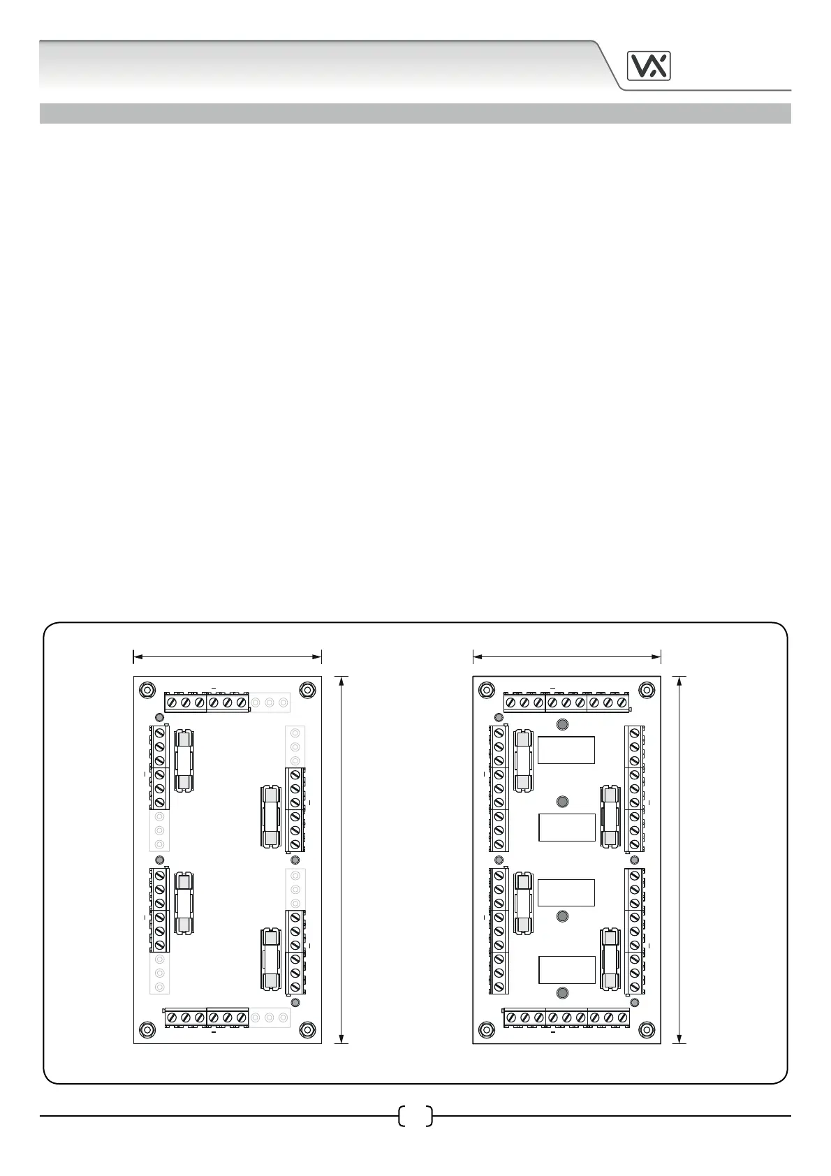
74mm 74mm
135mm
135mm
VX123-A / VX123-V AUDIO AND VIDEO 4 DOOR SWITCHING CARDS
Audio cabinets will include a VX123-A 4 door audio switching card and video cabinets will include the
VX123-V 4 door video switching card.
Each switching card requires 12Vdc power and will be pre-wired from one of the 12Vdc outputs on the
UBPSU5.0 psu. It has four fused (tted with a 1A, 20mm ‘quick blow’ fuse) door input/output terminals that
includes a status LED to indicate when there is a fault with the input/output (when the LED is ON this indicates
the input is ok, when the LED is OFF this indicates the fuse is damaged or blown). Each set of door input/output
terminals include connections for the following:
• 12Vdc/GND power output to power each door panel (fused connection on 12Vdc terminal).
• L/- databus connections from each door panel (common ‘through’ connection).
• Busy connection from each door panel (common ‘through’ connection).
• Trade output to each door panel (common ‘through’ connection).
and for the VX123-V video switching card three additional terminal connections:
• SL switching signal from the door panel to switch the V1/V2 balanced video signal through the
corresponding door input/output position on the switching card.
• V1/V2 balanced video input signal connection from door panels camera module (switched connections).
Also included are common output connections to connect the card to audiophones/videophones or allow
the card to be connected in series with another switching card should the system comprise of more than 4
doors (for video systems using the VX123-V three additional ‘through’ connections are included: V1, V2 and +20V).
VX123-A / VX123-V Dimensions
VX123-A VX123-V