CONTROL CABINETS - TECHNICAL MANUAL EN-UK - V.1.3 - 14/07/16
DE
27
AUDIO & VIDEO CONTROL CABINETS
MOUNTING THE CABINET
The CAB1 and CAB2 cabinets are suitable for xed installations only and should only be tted to solid walls.
Where possible they should be located at a central point (typically in a riser cupboard or small electrical room).
The other components that make up the system (e.g. audio/videophones and intercom door panels etc.) can be
cabled back to the cabinet. Remember the cabinet will need to be located close to a mains point.
Before xing the cabinet to the wall it is recommended that the cabinet knockouts that will be required are
removed rst and suitable grommets tted where necessary.
Removing the Cabinet Knockouts
IMPORTANT NOTE: Due care should be taken when removing the cabinet knockouts to avoid personal
injury. Appropriate hand tools should be used and appropriate hand and/or eye protection used.
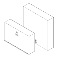
• First select the cabinet knockouts required (refer to pages 5 - 9 for knockout locations).
• Next take a at-head screwdriver and use the at end to gently tap out and apply pressure to the
knockout xing (see Fig.1A and Fig.1B).
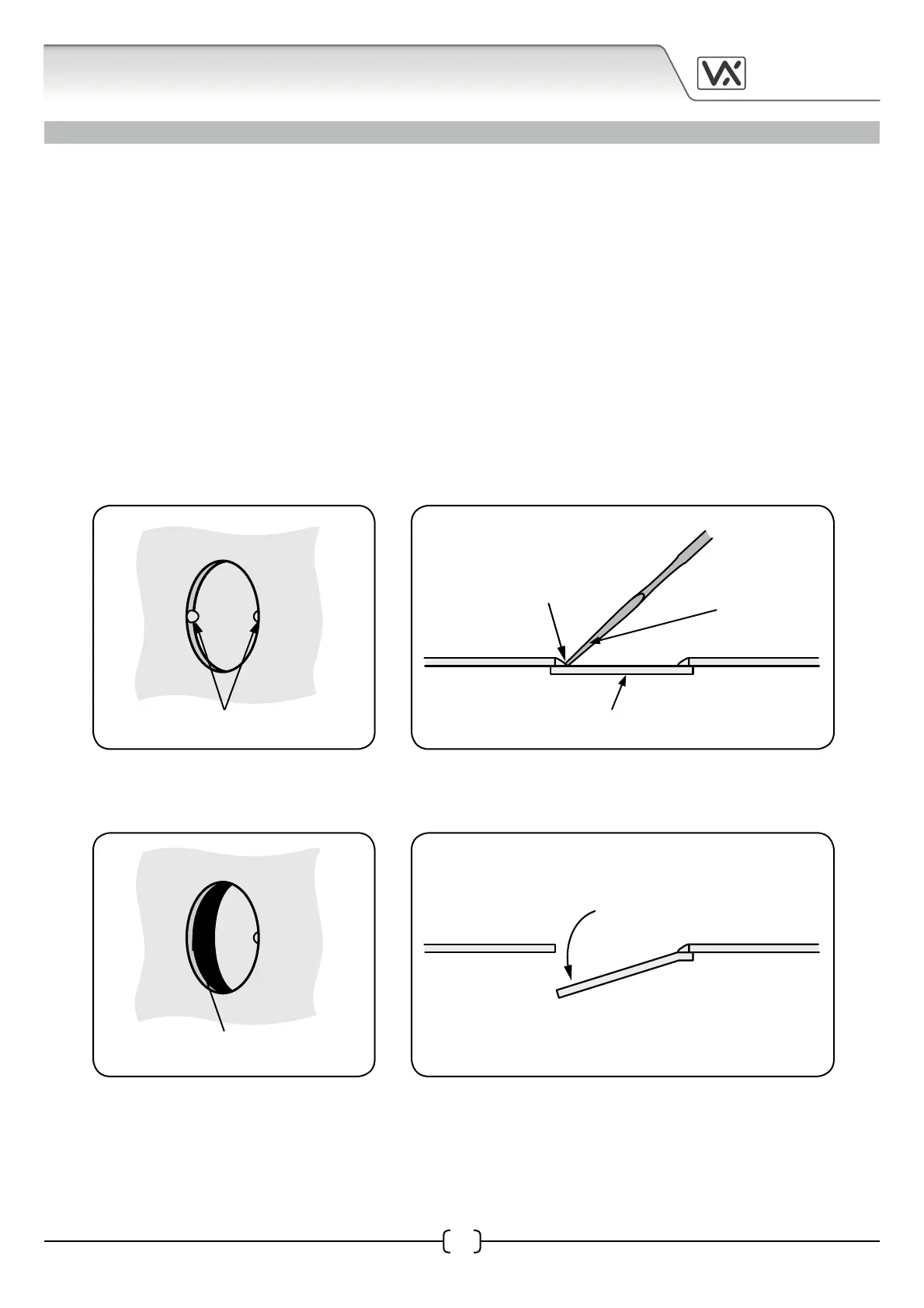
• Once the knockout xing has been removed (refer to Fig.2A) push down on the knockout cover
(see Fig.2B).
• Next take a set of pliers and grip the end of the knockout cover and ease it back and forth until the
other knockout xing fatigues and the knockout cover breaks away from the cabinet (see Fig.3A
and Fig.3B).
Fig.1A
knockout xings
Fig.1B
knockout cover
at-head screwdriver
tap out and apply
pressure to the
knockout xing
Fig.2A Fig.2B
push down on the
knockout cover
knockout xing
removed