CONTROL CABINETS - TECHNICAL MANUAL EN-UK - V.1.3 - 14/07/16
DE
28
AUDIO & VIDEO CONTROL CABINETS
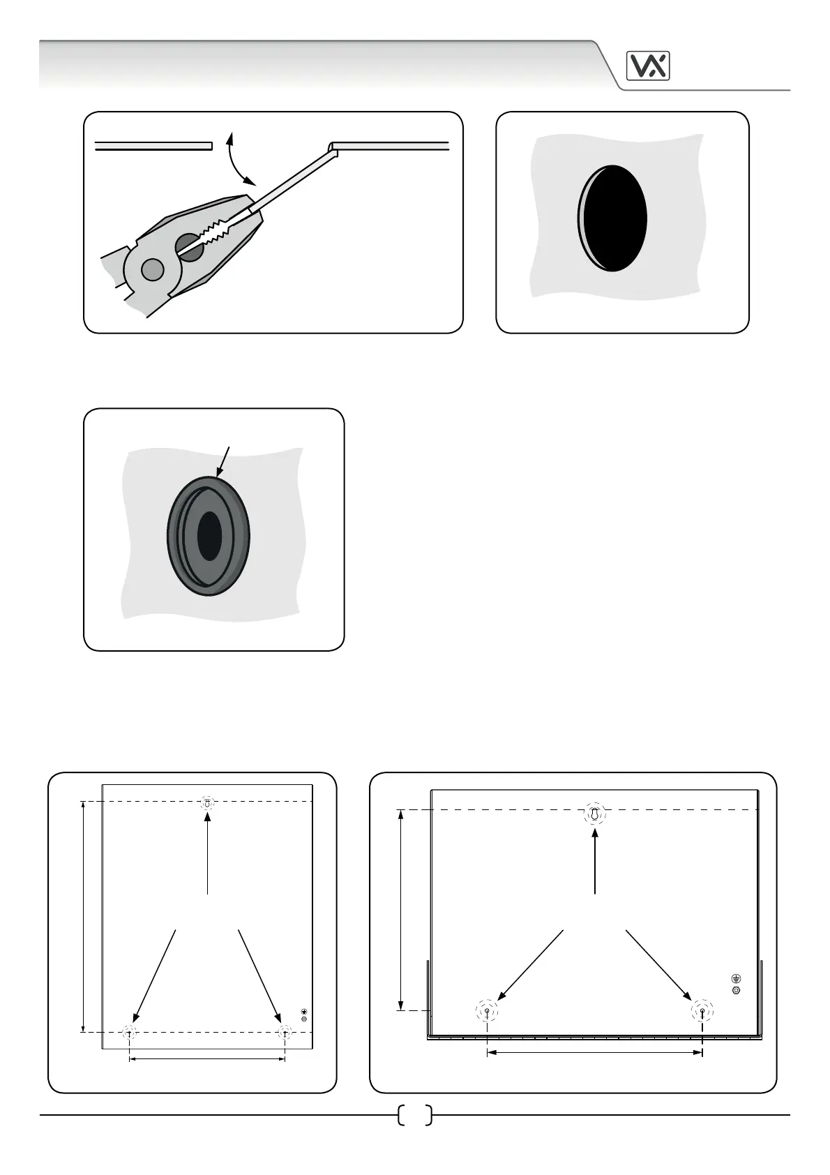
• If necessary le down and smooth out any rough edges on the knockout hole and then t a
suitable size grommet (see Fig.4).
Fixing the Cabinet to a Solid Wall
The CAB1 and CAB2 cabinets have a single 7.5mm mounting hole on the base of the cabinet plate located at
the top centre and two 5.5mm mounting holes located near the bottom left and right corners of the cabinet
base (see Fig.5A for the CAB1 and Fig.5B for the CAB2).
Fig.3A Fig.3B
Fig.4
t a suitable size grommet
into the knockout hole
ease knockout cover
back and forth
Fig.5A Fig.5B
mounting holes
template
260 mm
403 mm
260 mm
210 mm
mounting holes
template