CONTROL CABINETS - TECHNICAL MANUAL EN-UK - V.1.3 - 14/07/16
DE
30
AUDIO & VIDEO CONTROL CABINETS
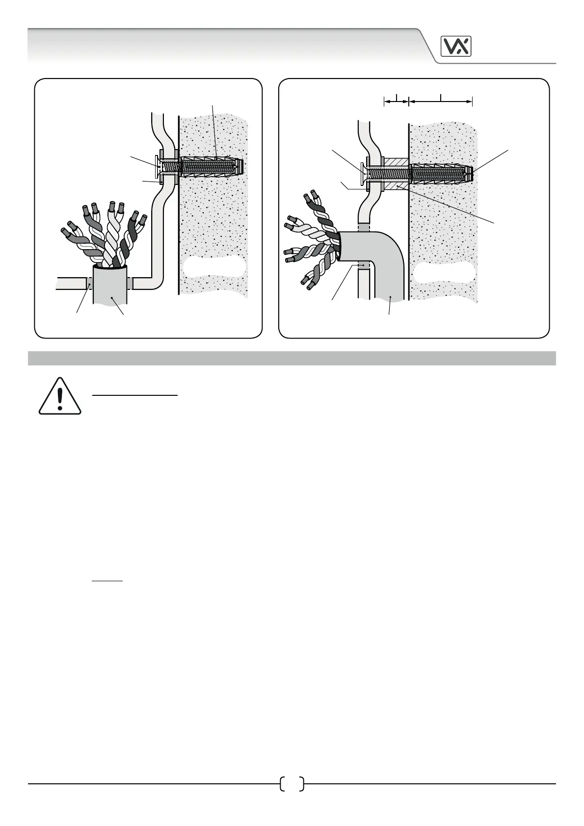
10-15mm 35-40mm
SOLID WALL
incoming
cable
rear knockout in
cabinet base plate
35-40mm, Ø6mm
nylon rawl plug
50-60mm, Ø5mm
self-tapping
countersunk
masonry screw
10-15mm,
internal Ø6mm
nylon spacer
M5 washers
SOLID WALL
incoming
cable
knockout at
bottom of cabinet
35-40mm, Ø6mm
nylon rawl plug
40-50mm, Ø5mm
self-tapping
countersunk
masonry screw
M5 washers
CONNECTION TO MAINS, SAFETY AND GUIDANCE NOTES
IMPORTANT: PLEASE READ THESE INSTRUCTIONS CAREFULLY
BEFORE COMMENCING WITH THE INSTALLATION.
DO NOT install any Videx product in areas where the following may be present or occur:
• Excessive oil or a grease laden atmosphere.
• Corrosive or ammable gases, liquids or vapours.
• Possible obstructions which would prevent or hinder the access and/or removal of the Videx product.
Videx recommends that any cabling and Videx product be installed by a competent and qualied electrician,
security installation speclialist or communications engineer.
The system MUST be installed in accordance with the current I.E.E regulations (in particular I.E.E Wiring
regulations BS7671), or the appropriate standards of your country, in particular Videx recommends:
• Connecting the system to the mains through an all-pole circuit breaker (refer to Fig.7) which shall have
contact separation of at least 3mm in each pole and shall disconnect all poles simultaneously.
• That the all-pole circuit breaker shall be placed in such a way to allow for easy access and the switch
shall remain readily operable.
• Ensuring that the mains supply (Voltage, Frequency and Phase) complies with the product rating label.
• Isolating the mains before carrying out any maintenance work on the system.
Mains Connection
Fig.6A Fig.6B