66250457-EN - V5.1 - 31/08/20
- 12 -
VK4K/6256 Series “6 wire Bus” videokit
VK4K/6256 Series - Installation handbook
Art.4833/4833X Speaker unit
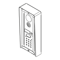
HOW TO CONNECT ELECTRIC LOCK
The “door-open” relay can operate either as “dry contact” or “capacitive discharge” mode.
• In “dry contact” operation mode the relay works in a traditional way, a power supply or a power source is needed to operate the
lock (12-24Vac/dc 2A max), and activation lasts according to the door opening time programmed.
• In “capacitive discharge” operation mode the relay’s contacts, when active, supply directly the lock (12Vac/dc 1A max) for a mo-
ment. You don’t need a power supply for the lock and the door opening time programmed does not aect the activation time.
A possible deterioration of the mechanical performance of the electric lock, might cause the “capacitive discharge” to malfunction in time. In case
the electric lock is used in very dusty environments or in peculiar climate conditions, we suggest to use the lock in dry contact mode.
12Vac/dc 1A Max
Fig. 5 Using capacitive discharge
12Vac 1.6A Max using Art.321
24Vac/dc 2A Max using other power supplies
Fig. 6 Using separate P.S.U.
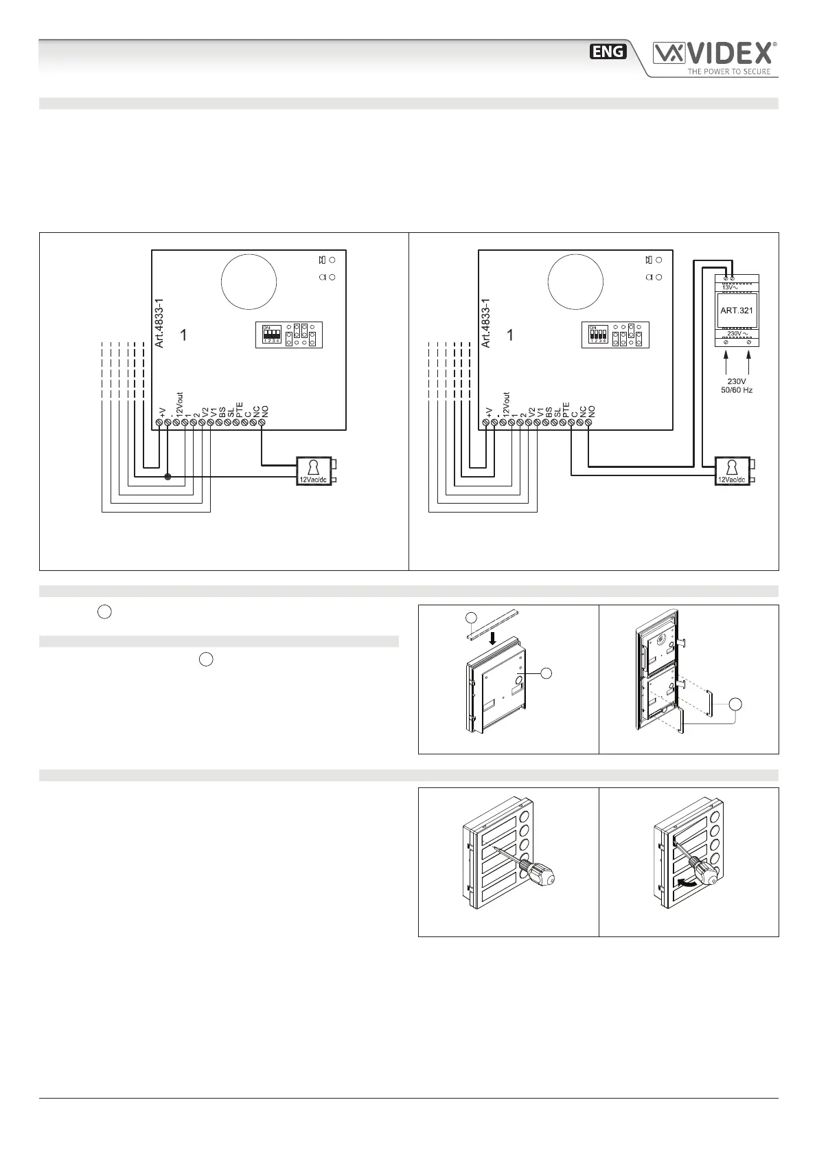
ADHESIVE GASKET PLACEMENT
Apply the
Y
seal as shown in Fig. 7.
ANTITAMPERING LOCKS FIXING
Fit the anti-tampering locks
W
as shown in Fig. 8.
Y
G
Fig. 7
W
Fig. 8
HOW TO REMOVE/INSERT THE CARD NAME HOLDER
• To avoid damage to the module front plate, mask the side
that will be in contact with the screwdriver blade;
• Insert the screwdriver (at side) into the card-holder hole as
shown in Fig. 9;
• Move the screwdriver to the left as shown in Fig. 10 to ex-
tract the card name holder;
• Edit the card name then replace it inside the holder and ret:
insert the holder inside its housing from the left or right side
then push the other side until it clips into place.
Fig. 9 Fig. 10
 Loading...